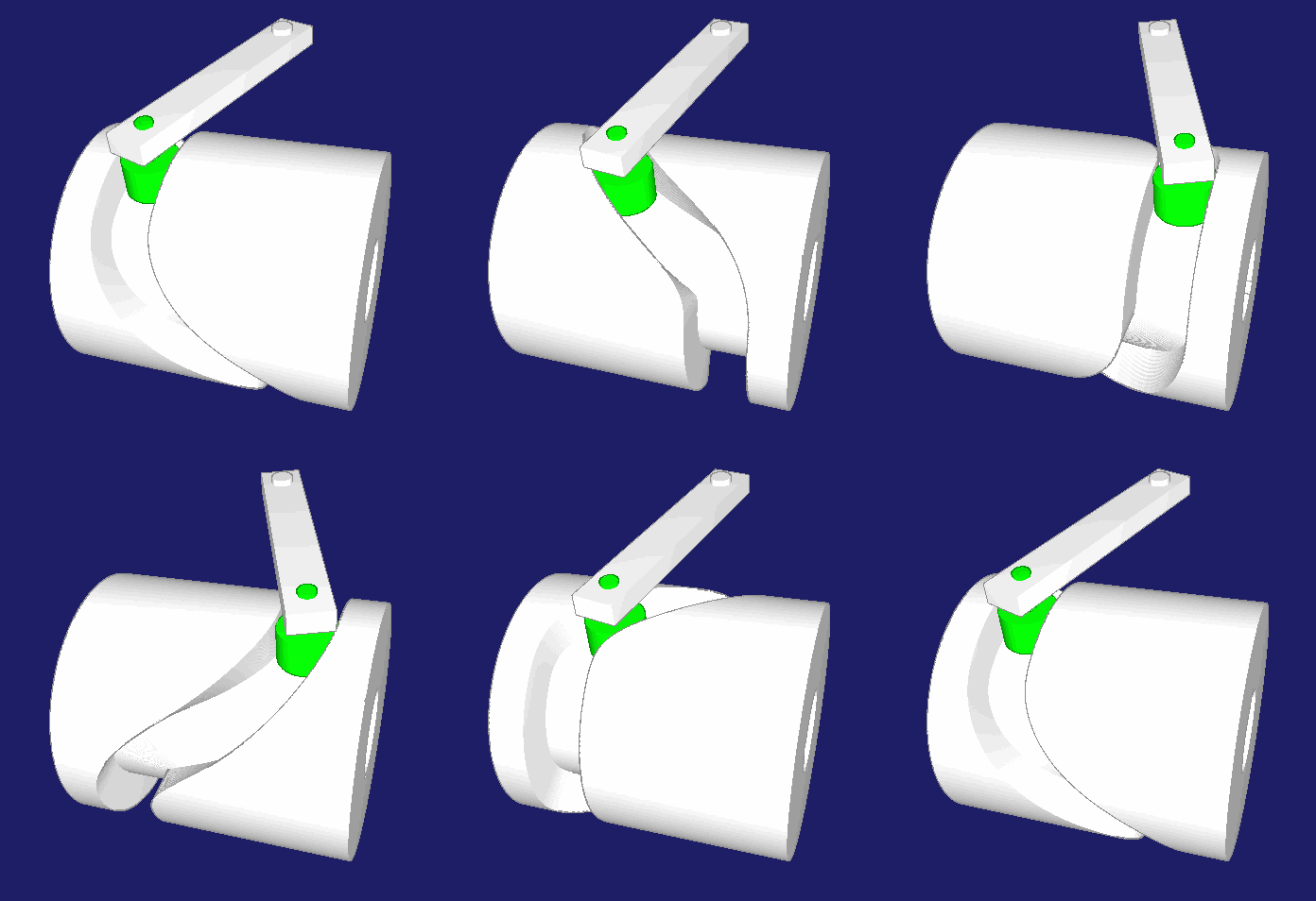
Cylindrical Cams (Barrel Cams)
Cylindrical cams are, next to cam disks and globoidal cams, a very common type of cams. Cylindrical cams are used when the output motion is to be essentially parallel to the cam axis of rotation. In contrast, the output of planar cams usually moves perpendicular to the cam axis.
Mechanisms are often made as simple as possible, with as few parts and joints as possible to minimize backlash and elasticity. In a complex cam driven machine, of course you can control all movements with cam disks, but for the output movements parallel to the cam axis you will then have to use spatial linkages for motion deflection. The rod ends in it have slack and harm the dynamics of the machine. Therefore, it is often better to generate such movements parallel to the cam axis in a direct manner with a cylindrical cam.
We would like to calculate and optimize cylindrical cams for you and provide you with NC and CAD data.
Cylindrical cams are also often used in indexing cam gears. There are two variants:
- Constant speed at the drive and a transfer function for the stepping movement
- Transfer function with constant slope ("cylindrical worm") and controlled drive with servomotors
In the second case, too, it is necessary to determine the shape of the cam edges correctly by cam calculation, because the constant gradient usually refers to the rotational movement of the output gear! Cylindrical cams with constant angular velocity referring to the rotating follower do not correspond to a spindle with a constant slope in which the rollers run linearly directly over the cam axis!
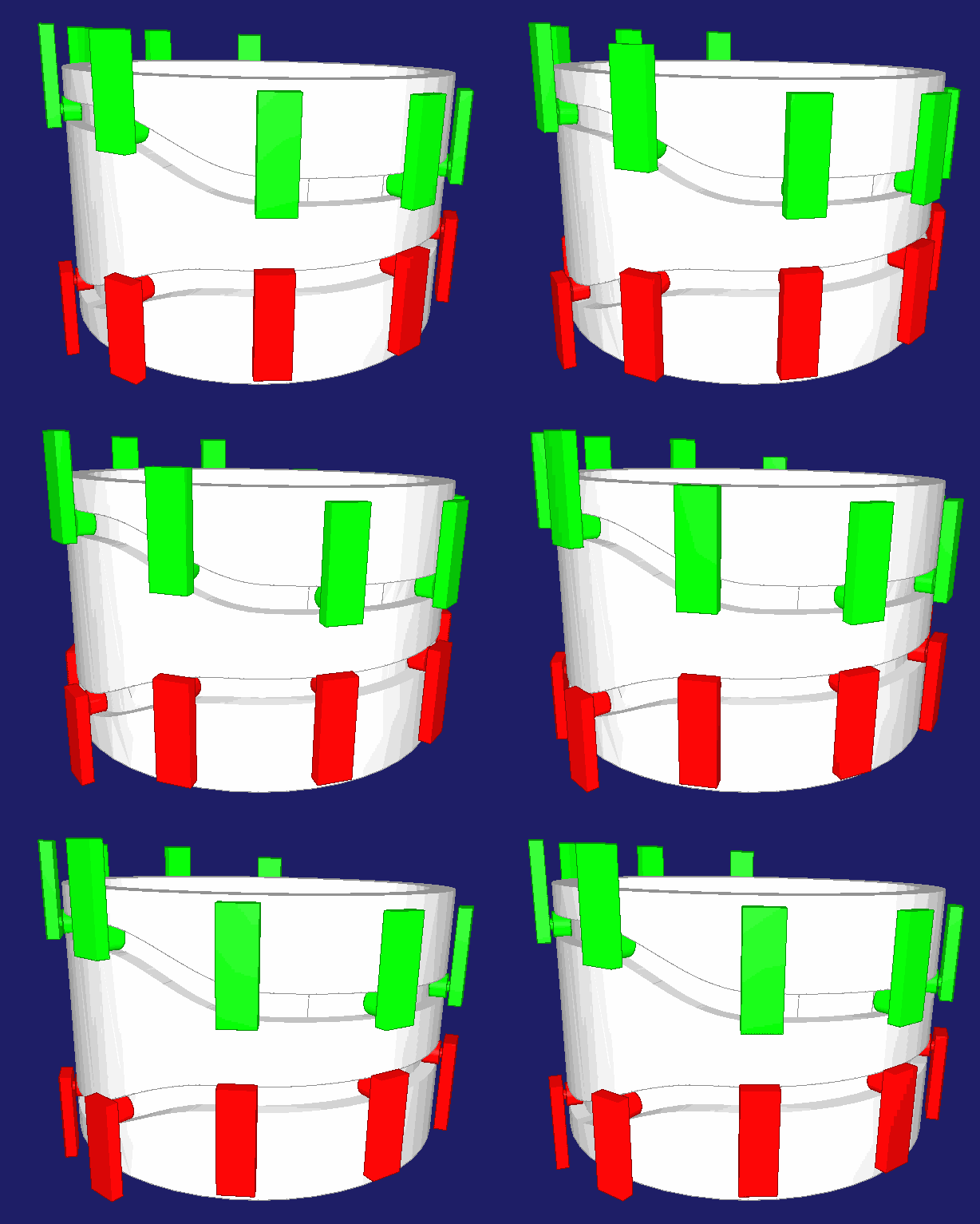
Furthermore, fixed cylindrical cams with multiple circumferential taps are often used in rotary machines:
The articles, often bottles or cans, are meandered around several carousels. For example, bottles can be filled, capped or labeled at full speed. Cans can be shaped, filled and crinkled.
Continuous operation leads to very high performance.
Advantages of cylindrical cams:
- Movements parallel to the drive axis directly accessible,
- with a compact and rigid construction
- high flywheel mass (advantage at constant drive speed)
Disadvantages of cylindrical cams:
- High self-inertia (disadvantage with drive with servo or emergency stop)
- More difficult to produce (4- or 5-axis machining), thus more expensive
- Complicated spatial cam flank geometry must be taken into account when extruding the cam track in 3D-CAD
- The rolling contact between cam and roller is always interfered with sliding, resulting in higher wear
The spatial geometry is not trivial in cylindrical cams. Planar cams are much easier to handle in this regard.
We have been calculating cylindrical cams for decades and know the associated special questions (and answers).
We would like to support you in designing your cylindrical cams and in creating accurate NC and CAD data with our OPTIMUS MOTUS software or our consulting and calculation services.
Skip to ...
To the homepage of Nolte NC-Kurventechnik GmbH
Developed view
On drawings or for calculations for cylindrical cams, it is customary to refer to the developed view. The spatial camd paths are stretched into the plane. The cam is viewed from the outside for this projection.
The developed view is thus the outstretched-in-the-plane cam case, viewed from the outside.
The following mental picture should explain this:
Take a bottle with a label and use a pen to draw any "camd path" around it. Then you take a knife and cut across the label, at any point, in the longitudinal direction of the bottle. If the label is not fixed with glue, you now have two loose ends that you can pull tight until the label is stretched straight and tangent to the bottle. Looking now at the initially drawn camd path, you can see the development view.
The following animation shows this with an example:
- Left in spatial representation
- Right next to it in developed view presentation
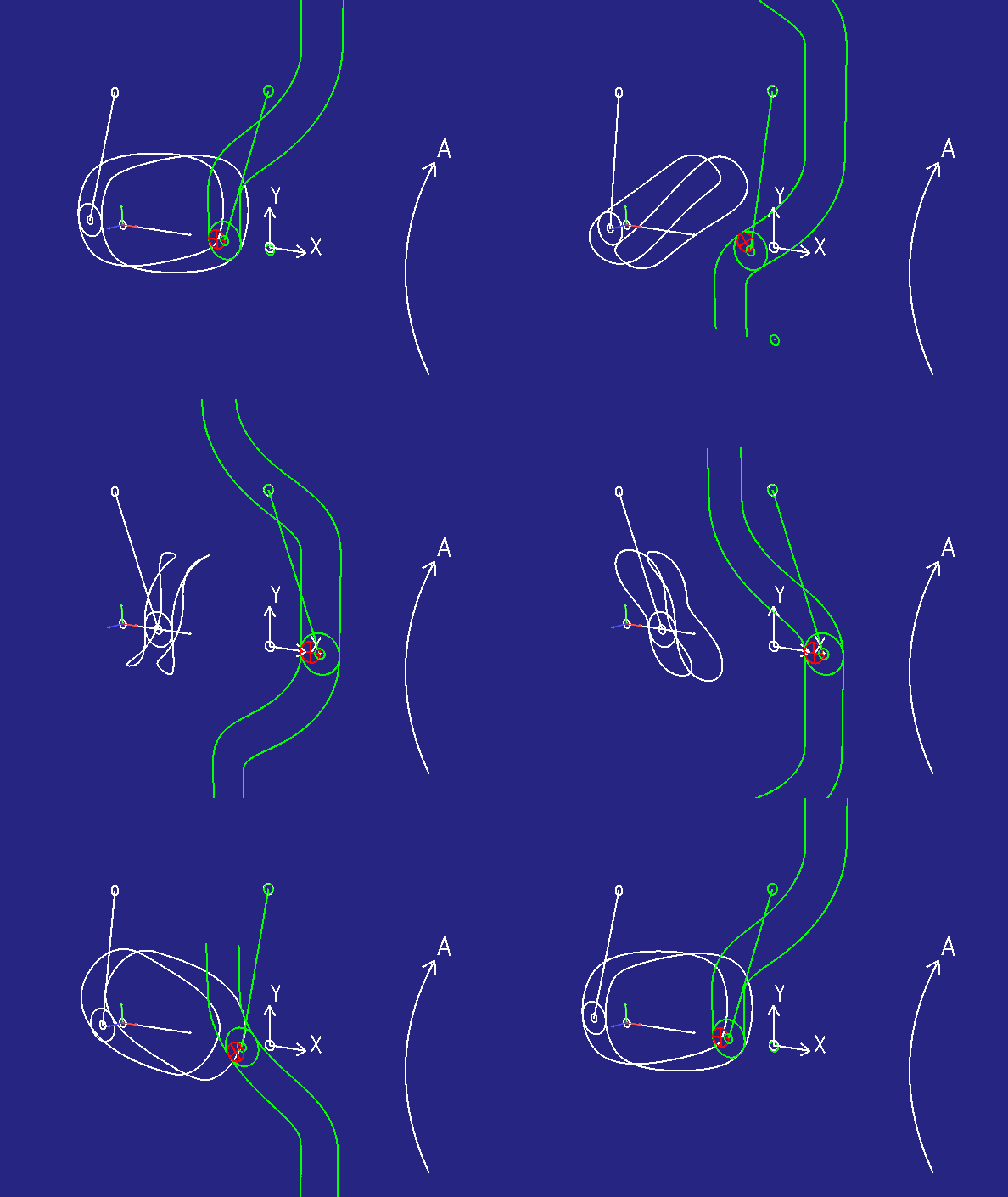
The smaller red circle represents a tool with which you want to mill the camd paths. The developed view can be used to calculate a tool radius compensation.
The developed view relates to a fixed diameter D on the cam.
Intuitively, the outer diameter of the cam or the cam edge is often used. To increase the manufacturing accuracy, it is better to use the pitch diameter as reference diameter. This is the diameter on the cam on which the generally crowned roller theoretically has contact with the cam, specifically when the point of contact in the plane of travel of the follower is just above the cam axis of rotation. Alternatively, the mean diameter of the cam flank is well suited as a reference diameter.
The developed view has a length of D•pi.
Flanks of cylindrical cams are virtually on the camd surface and cover a certain diameter range. They have a smallest, a largest and a pitch diameter. The developed views related to different diameters have different lengths. The shorter the developed view, ie the smaller the reference diameter, the steeper and more sharp-edged are all transitions.
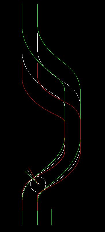
Cylindrical cams therefore sometimes have undercuts on the inner cam diameter, but consistently round transitions on effective and outer diameter. If cylindrical cams are free of undercuts on the effective diameter, a minor undercut on the smallest cam flank diameter can usually be accepted. However, it is a problem to extrude such geometry in CAD. Our OPTIMUS MOTUS software detects undercut areas and automatically replaces them with roundings when exporting 3D data.
Because of the cam slope depends on the reference diameter, ridges of cylindrical ridge cams become generally thinner with decreasing cam flank diameter. It is therefore possible in extreme cases that a cam ridge is sufficiently wide and stable on the effective and outer diameter, while you have a hole on the smallest cam flank diameter.
In the OPTIMUS MOTUS software, the cam edges are each calculated exactly on several reference diameters, so that an exact 3D model of the cam edges or the "roller trace volume" is available, which is also suitable for high-precision machining such as jig grinding.
Coordinate Systems
To calculate cylindrical cams and derive CAD and NC data for design and fabrication, you must refer to appropriate coordinate systems. These can be different for calculation, CAD data, NC metadata and on the NC control, which in practice easily leads to errors and misunderstandings. Especially when preparing NC data for concrete production machines, you have to be extremely careful that the axes are transformed correctly from the NC metadata.
When we calculate cylindrical cams, we create NC metadata in a well-defined coordinate system and in a neutral format, which is then converted by post-processors into machine-specific coordinate systems and data formats. In total, over time we have developed about 200 postprocessors that each generate data directly for a specific machine / control combination. Such a post-processor is a very secure way to generate NC data for milling or grinding cylindrical cams. In addition, there are a number of post-processors in neutral or widespread standard formats.
It is also important with which side the cam is clamped on the rotary table. If you swap the mounting side, the signs must be changed for all three programmed NC coordinates.
For the NC metadata we use the following coordinate system:
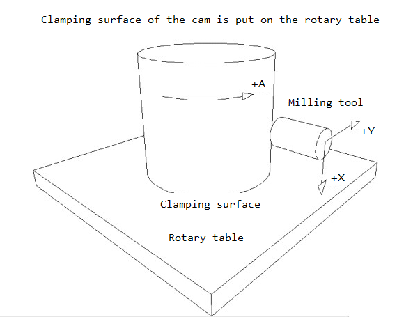
X = cam axis, main stroke direction
Y = central migration axis, perpendicular to X, in the plane of movement of the follower
A = cam angle or rotary table angle according to the left-hand rule (due to the kinematic reversal in the calculation)
To be able to prepare the metadata correctly for a tooling machine, it is best to stand in front of the machine with the sketch above, let the three axes for stroke, central migration and rotary table turn into "plus" direction and record the observed traversing directions and axis designations on the sketch.
Example: The tool is moved in the direction of the clamping surface (in our metadata + X) and you observe at the machine that the Z axis moves down (as an example!). So write down "-Z" on the sketch next to the "+X" for the metadata. So you determine empirically on the machine - which in our experience is the safest way - the transformation rule "Metadata +X is converted into machine tool -Z".
This is only an example! Your machine may have different transformation rules.
When exporting CAD data, the rotary table axis is not required; instead, the camd paths are usually generated as a point sequence with X/Y/Z coordinates that refer to a cam coordinate system.
For us, the X-axis of the cam coordinate system corresponds to the cam rotation axis.
The Y-axis (perpendicular to X) coincides with the Y-axis of the NC metadata at time phi = 0 (start of motion cycle and displacement plan). As the cam or rotary table rotates, the Y-axis of the NC metadata remains fixed relative to the environment, while the Y-axis of the cam component remains fixed relative to the cam.
The Z axis is determined according to the right-hand rule from X and Y: Z = X x Y. Z is perpendicular to X and Y.
For both coordinate systems (for NC metadata and for the CAD data) the origin lies on the cam axis of rotation.
Manufacturing
For the production of cylindrical cams, we apply the same accuracy standards as for planar cams. Discounts are permitted at most within the frame in which the round table introduces additional errors. Generally, we should claim a track accuracy of 0.02mm for planar cams and cylindrical cams as well.
If the required accuracy could not be realized, the reason is often not easy to find. In such a case we may be able to help with our experience.
Cylindrical cams are produced on tooling machines with a rotary table. At least four axes are interpolated simultaneously. The rotary table is needed to map the rotation of the cam around its axis.
In the case of a fixed cam with circumferential drives, one applies the "kinematic reversal". In theory the entire cam gear rotation is superimposed in such a way that the follower bearings are immobile, and instead the cam rotates. So you change the reference system and look at the world as if you were sitting on the slider or the rocker arm bearing.
A classic, conservative, careful and expensive strategy is always to finish cylindrical cams with a tool whose diameter corresponds to the roller diameter. The tool then replaces exactly the roller in engagement with the cam. If you prefer to use larger rollers with eg 52mm, 80mm or 110mm diameter, that quickly becomes costly. Then you always need a tool with exactly the nominal diameter for the last cut. If you sharpen the tool for example by 0.2, mm referring to the radius, the cam flank will not be correct anymore in the slope areas. Depending on the slope, you quickly get deviations of 0.1mm or more.
Moreover, there are two problems with groove cams:
1.) one flank is made in conventional up-cut milling and the other in climb milling, with a corresponding loss of quality
2.) at the starting point of the milling process, an edge will remain, an offset that disturbs the follower movement
Unfortunately, hardly any CNC control offers a tool radius correction by itself that can be used for cylindrical cams.
Therefore, we generate NC data for cylindrical cam flanks either for a specific tool diameter desired by the customer or producer (including tool radius compensation), or we generate NC programs that contain tool radius compensation in the form of parameter programming.
With parameter programming, the desired tool diameter can still be specified on the CNC machine when cutting the cam. Many cylindrical cams with a big roller diameter of, let's say, 110mm can be finished with the tool diameter 20mm (or 19.8mm, or 19.5mm), without unduly high deviations.
This considerably reduces the tool procurement costs! You use standard tools (eg diameter 12mm, 16mm or 20mm) that can also be re-sharpened.
When a cylindric cam flank is finished in one cut (as is usual), and when the tool diameter is smaller then the roller diameter, deviations between the theoretical cam profile and the produced cam will occur in the height of the cam flank, ie along the roller axis.
In the animation below "developed view" (see above), the red circle represents a tool. Opposite the center of the roller, it must always be deflected perpendicular to the camd path in order to reach the theoretical cam profile. However, the corresponding deflection direction depends on the cam flank reference diameter!
If you want to finish a cam flank in one cut, in opposition to cutting many thin lines one after the other, you have to set one reference cam diameter and thus one deflection direction. Deviations occur on all other cam reference diameters. These deviations always lead to too much material on the cam flank, so that grooves become narrower. The steeper the cam, the higher the cam flank and the larger the difference between roller and tool diameter, the greater will be the deviations. The deviations increase approximately quadratically with the difference to the reference cam diameter. If one refers to the working or pitch cam diameter or the mean cam flank diameter, relatively small deviations arise.
Cutting cam flanks in many turns with a crowned or spherical tool, each turn on a somewhat smaller reference diameter, is unattractive, because the milling path is very long and longitudinal edges on the cam edge arise that worsen the contact pattern of the roller. Multiple cuts with a cylindrical tool are equally unattractive.
Our software OPTIMUS MOTUS estimates the deviations that occur when finishing a cylindrical cam with a smaller tool. So we are sure that we do not produce inadmissibly high profile deviations with our desired tool diameter. Often, these deviations are very small (less than 0.01mm), even if the difference between roller and tool diameter is very large (eg 110mm to 20mm).
But we also had critical cases with a calculated deviation of 0.8mm. In such a case, one must actually use a tool diameter that is close to the roller diameter, or use the NC optimization, which will be further explained in the text.
Cam rollers are often crowned, so that the roller diameter at the edges is slightly smaller than in the middle. Very often, the roller diameter tapers faster with the distance to the roller center than the corresponding allowance for the cam increases. The contact pattern between the cam and the roll looks like this:
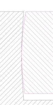
It is getting critical when the profile deviation along the roller axis grows faster than allowed by the crowning radius of the roller. Then the roller always runs with only one edge on the cam, and, with a groove cam, the transmission even jams.
If you can use a fifth axis to pivot the tool during cam production (often the B axis), this degree of freedom can be used to reduce profile deviations.
Our OPTIMUS MOTUS software offers the option of optimizing NC data with four or five axis in such a way that the profile deviations become minimal. With a cylindrical cam and the use of standard tool diameters, the profile deviations can be drastically reduced in this way compared to the four-axis machining.
Chamfers
When milling cylindrical cams, sharp edges are first created between the outer case and the cam flanks. It is common to deburr these edges with a file or the Flex. But this is very time consuming, and the hand deburred edges do not look very nice either. With special NC programs for conic tools, these edges can be deburred programmatically. The spatial geometry and thus the NC post-processors work a little differently than with the cam edges.
It creates clean, uniform-looking chamfers of defined width, so that the cams look immediately higher quality. In addition, no one has to laboriously edit the edge by hand, so that the production costs are reduced.
CAD processing
In order to achieve a good CAD model of a cylindrical cam, we calculate the cam flanks on 2 or more reference diameters exactly and use these 3D curves for extruding the "roller trace volume". The roller trace volume is the room that the roller would cut away from the cam body.
If you subtract the roller trace volume from the raw cam body, you obtain a solid model of the cam.
A correct solid model of the cam is required if CNC data is to be derived from it using an CAM programming system.
In the past, the NC data for cylindrical cams were generated directly during the cam calculation. Today it is very common to first create a solid of the cam and then derive NC data from that.
Our software OPTIMUS MOTUS provides exact data to extrude cam solids suitable for cam production.
Possible Errors
Experienced cam calculators and produders will usually produce neat, well-running barrels cam gears when combined.
However, if one of the participants misses the experience, mistakes often occur that lead to the transmission not running at all or only poorly.
Nobody anticipates mistakes until the test run in the machine. In retrospect, finding the mistake(s) requires a lot of experience and analytical skills.
In an open cylindrical cam with only one cam flank, sometimes calculation, manufacturing or assembly errors are not immediately noticeable, because the roller always makes it somehow over the cam flank. But then the contact pattern between cam and roller is not correct, and there may be much wear. In addition, the follower does not move as dictated by the calculation.
For positive cams (groove cams or ridge cams), most potential errors not only lead to poor contacts, but also to jamming of the gearbox, ie it does not run at all. Clamping could be eliminated simply by taking back the cam flanks by a certain amount. However, this leads to slack during operation and thus to shocks.
Slack is very bad for the dynamics of the cam gear.
There is only one way to good cylindrical cam gears: calculate, manufacture and assemble correctly!
In case of cases, here is a checklist of common error possibilities, especially for cylindrical cams:
- Wrong kinematics (eg lever installed, but calculated with ram)
- Calculated with incorrect kinematic dimensions
- Eccentric bolts used, but not included in the calculation
- Tool diameter too small for slope, flank height and roller diameter
- Coordinates are not transformed correctly, especially the center migration axis
- No correct equidistant calculated, NC data rather shifted parallel to the axis
- Cam mounted the wrong way around (that should be excluded by the engineers!)
- Spatial geometry of the contact between roller and cam is not considered correctly
- Wrong extrusion type used in CAD
- Reference curves for the extrusion in CAD determined incorrectly
- Rotary table has slack
- Cylinder case unwinding function of the CNC control used
Special Designs
Finally, pictures of special designs, which we can calculate with our software, and which are related to cylindrical cams:
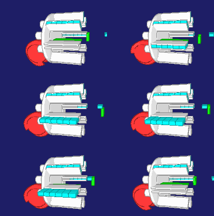
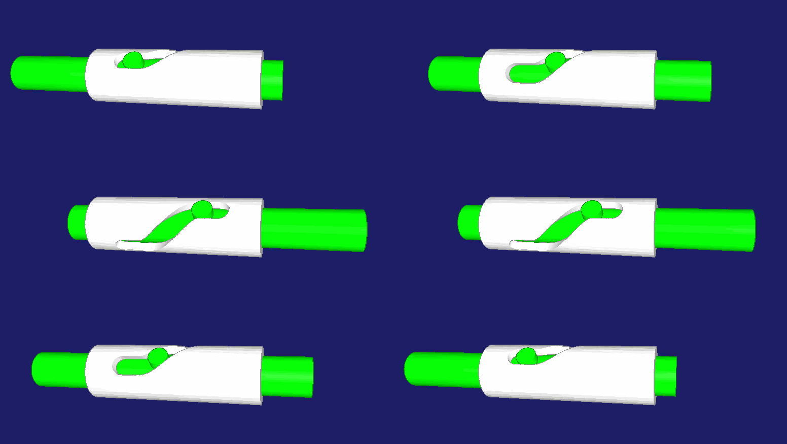
An output carriage does not necessarily have to travel parallel to the cam axis of rotation:
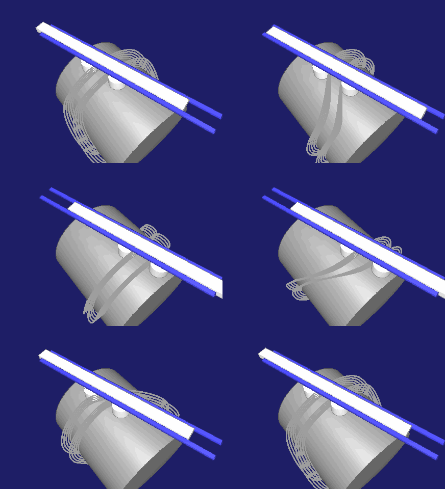
The role of output and drive can also be reversed. In the following animation, the piston is driven, eg by a pneumatic cylinder or press ram, and the rotation of the cam is used for the motion control.
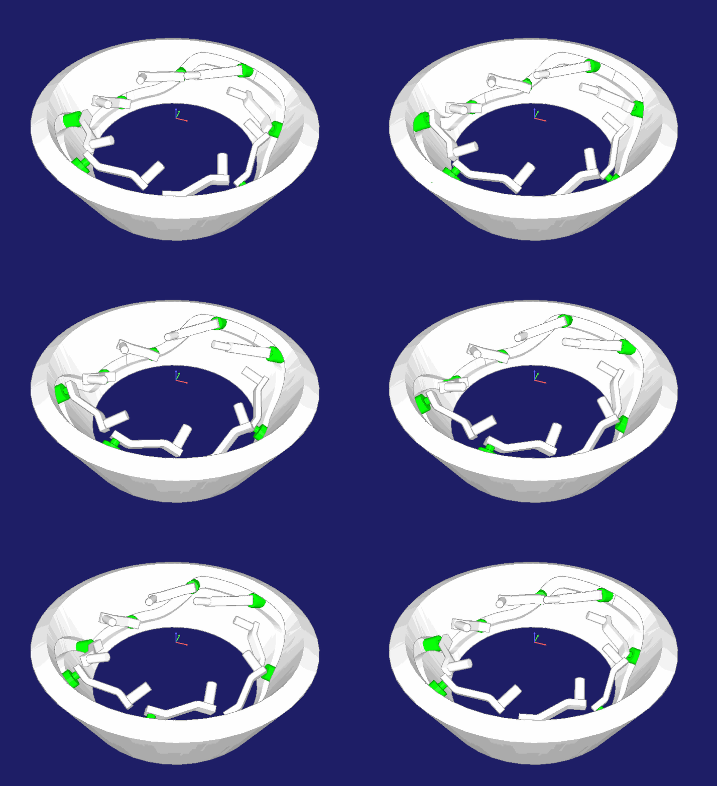
Cam tracks can also be kinematically calculated and manufactured on the inside of a conic ring. Transmissions of this type are used, for example, in machines that braid cable sheathing:
To the homepage of Nolte NC-Kurventechnik GmbH
Start Mechanisms CamDesign Indexing Training Servo+PLC MotionDesign Software Service CamCalculation Imprint PrivacyPolicy
DevelopedView Coordinates Cutting Chamfers CAD-Files PossibleFaults Specials
11/06/21
• Software OPTIMUS MOTUS ® /
DasNolte ®
• All types of Cam Calculations
• Performance Optimizations
• Trainings and consulting
• App and Software Development
• PLC Motion Software
Cams, Mechanisms, Motion Design. Faster Machines. Since 1965.
