Planar cams
Cams are very common mechanical components for controlling movements. They are always part of a cam mechanism.
We would like to calculate cams for you. Send us your inquiries!
We have decades of practical experience in cam calculation and an optimal calculation tool (OPTIMUS MOTUS) available.
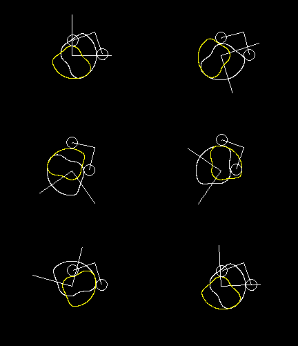
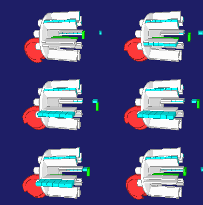
Cam gears are planar mechanisms, in contrast to the cylindrical and globoidal cam gears. Therefore, cam plates are relatively easy to manufacture. You do not need a CNC rotary table and no tool swivel axis for milling. Instead, the cutting tool only needs to be coordinated in two axes (X / Y, X / Z, Y / Z or C / X). NC data usually refer to the cam profile. The machine control calculates the tool center path automatically via the tool radius compensation.
In general planar cam gears, cam and roller may move arbitrarily in the plane and relatively to each other. For cam disks, however, you can assume a rotating cam.
Cams can be found, for example, in the following applications:
- Packaging machines
- Assembly machines
- Lathes (index machines)
- Automotive valve trains
- Parallel cam indexers
- Bending machines
- Punching machines
- Industrial sewing machines
- Pick&Place automats
- Embossing machines
- Presses
Corresponding to the mechanical cam, which generates an oscillating output movement from an input rotary motion, there is also an "electronic cam" in servo drive technology. This means a function in a servo-controller which generates a corresponding slave signal from a master signal with the aid of a stored transfer function.
Mechanical cams are very powerful machine elements for motion control.
In a complicated interaction of movements, as is typical for packaging machines, assembly systems, bending machines etc., mechanical cams achieve the highest cycle speed and the shortest cycle times ever.
Mostly we are dealing with cam gears where the cams rotate at a constant speed, and where the output levers or sliders are mounted in a rotating or sliding manner in the frame. But that is not absolutely necessary for us.
In our calculations, we also consider uneven drives and motion overlays.
Example:
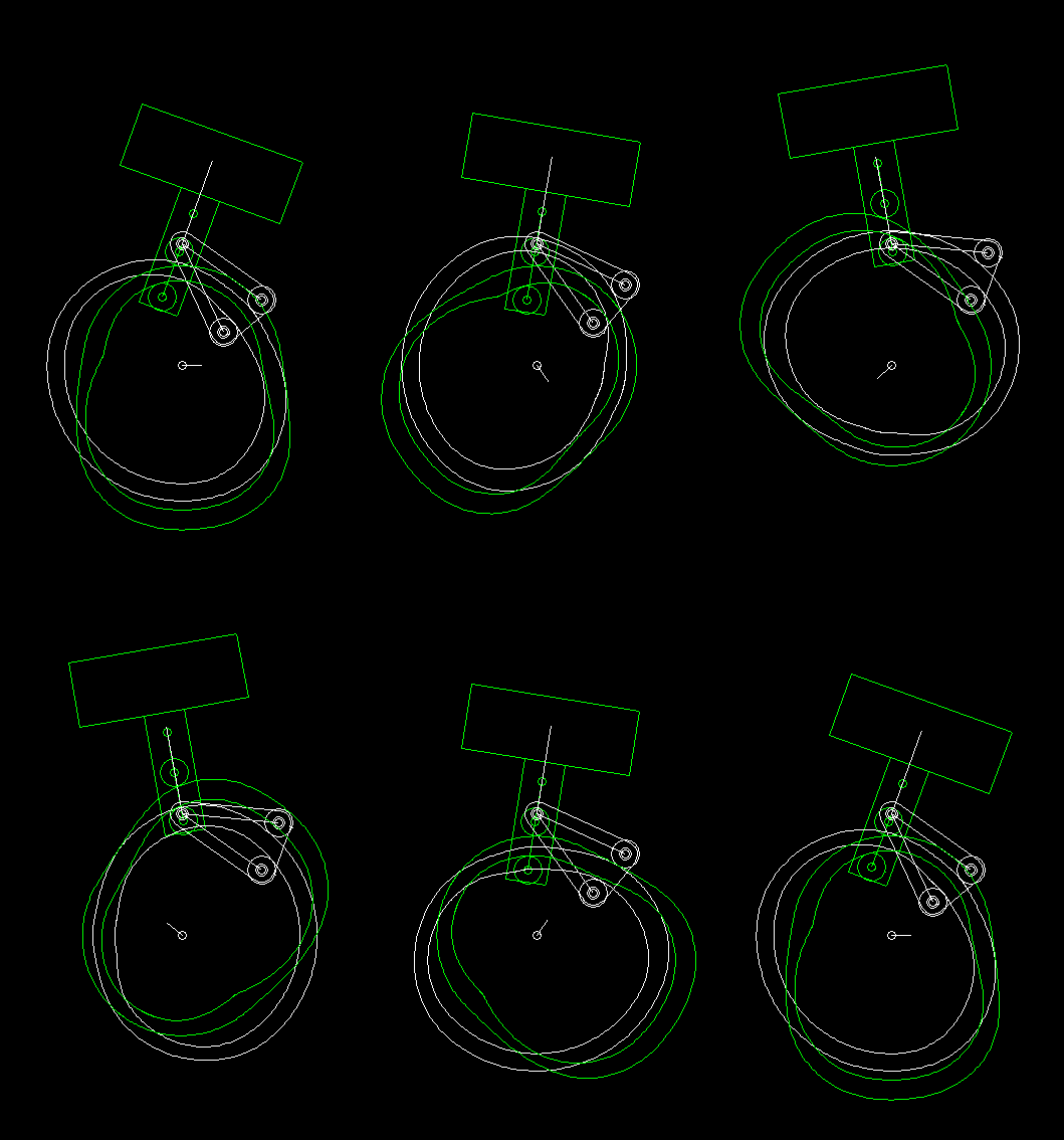
This example contains several special features:
1. The radially deflected carriage is mounted with a linear guide on the cam lever, and both rollers are mounted directly on the carriage. Due to the simple mechanical design of the lifting / swiveling mechanism, the overlapping of the swivel and the lifting movement must be taken into account when calculating the lifting cam (green).
2. The drive of the cam is not even. The cam is accelerated from standstill to maximum speed, then executes the swing-stroke cycle and stops after one revolution.
3. It should be noted that the two cam edges are not equidistant!
Fixed cams can be scanned by a plurality of evenly distributed drives, similar to a carousel, and are thus very well suited for continuous operation. The high performance is then very inexpensive by the multiple sampling.
Example:
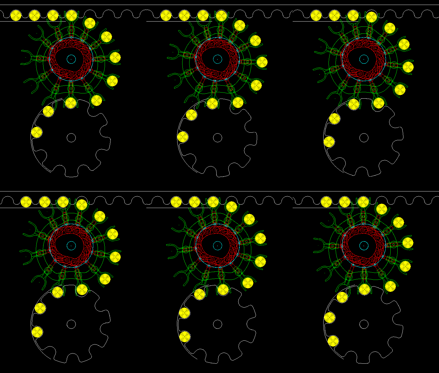
Transfer from a conveyor belt to a transport wheel
The animation shows the transfer of articles from a uniformly running conveyor belt (top, shown in white) in a transport wheel (below, also shown in white) in continuous operation. Grippers (green) push over the articles, hold the articles firmly (eg with vacuum) and pull them out of the belt. Below, the grippers synchronize, each with a gap of the transport wheel, lead the articles into the gaps and finally retire. All deliveries run collision-free and jerk-free with the help of two fixed groove cams. A cam (red) is used for the pivoting movement of the grippers, mainly for synchronization with conveyor belt and transport wheel. The other cam (green) controls the grippers radially. In continuous operation, several gripper systems each engage with levers and slides in the groove cams. Due to the multiple sampling, very high yields are achievable. Both groove cams do not overlap, so they can be milled in one plane or in the same base plate. Although everything looks very tight, there is room for 12 gripper systems.
Overall, you get a very compact and very powerful transfer gear.
Another advantage with cams is that the movements are automatically executed correctly:
- Referencing is not required
- Nothing can be wrongly programmed in the process
- Defects in electronic components are irrelevant
Machines with mechanical cams are accordingly easy to commission.
With a cam control, there is also no electronics for which after a few years perhaps you cannot procure a substitute. You will always be able to recreate a worn cam as a single part.
Cams can also be combined with servo drives or coupling gears (linkages).
Cams are flat, they require little space.
Their moment of inertia is therefore significantly smaller than that of cylindrical cams or globoidal cams with comparable transfer function. This is important for a quick emergency stop or a quick start from standstill.
For the professional design, calculation and optimization of cam discs we use the software OPTIMUS MOTUS.
When we calculate cams, we refer to drawings (DXF, DWG, Tiff, pdf) or STEP files. In the concept phase, sometimes even a hand sketch and a few explanations via e-Mail do it.
You define the desired motion at the output of the mechanism and possibly also the cam rotation motion profile, optimize the motion design and calculate the cam contour(s). In a graphical editor, you optimize the movement for low velocities, accelerations and drive torques. You evaluate the cams with regard to transmission angle, radius of curvature, bearing force, Hertzian pressure, drive torque and durability. Finally, you export NC files (ISO, Heidenhain, etc.) for production or CAD data (DXF, STEP, etc.) for engineering.
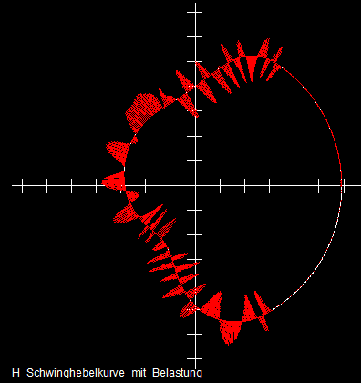
The following two pictures show evaluations for a double cam disc with swing lever output. Such a pair of cams is also called: complementary cams, conjugate cams, working cam and return cam, main cam and counter-cam.
Double cams are particularly powerful transmissions, because both rollers can be supported on both sides (symmetrical load distribution) so that cylindrical rollers can be used. The roller has contact over it's whole height then, not just at one point, and relatively small Hertzian stresses occur. In addition, the slack in the cam gear can be optimally adjusted by eccentric bolts or other adjustment options for the roller center distance. Possibly slack can be completely eliminated. This is important especially at high speed rates.
As a rule, we issue circularly interpolated manufacturing data for cams. The cam contour is depicted as a sequence of arcs and straight line segments which merge tangentially into one another. The milled or ground cam flanks are very smooth this way, without facets, and the NC programs very compact, but still accurate. For the output of manufacturing data, we use about 200 different postprocessors.
Incidentally, OPTIMUS MOTUS can also import NC files again. This makes it possible
- to generate NC data for the same cam for another CNC machine
- to simulate which motion diagram has been implemented on the cam described in the NC file
- to check whether the main and reverse cams, which are produced with two NC programs, work together correctly
You might think that the quality of cam production increases if you just put more points in the NC file. However, if the point density is too large, then the NC controller will not be able to calculate the point sequence according to the specified milling feed. Especially older controllers then stop the tool for a short while in order to calculate the next steps. The tool then slowly moves into the camed path, creating very ugly chatter marks. To avoid this, our software optimizes the length of the single NC segments.
We would like to calculate and optimize cams for you at a fixed price and provide you with NC and CAD data!
We can look back on more than 45 years of experience from more than 14000 calculations.
To the homepage of Nolte NC-Kurventechnik GmbH
Start Mechanisms Kinematics CamDesign Indexing Servo+PLC MotionDesign Training Software Service CamCalculation Imprint PrivacyPolicy
11/06/21
• Software OPTIMUS MOTUS ® /
DasNolte ®
• All types of Cam Calculations
• Performance Optimizations
• Trainings and consulting
• App and Software Development
• PLC Motion Software
Cams, Mechanisms, Motion Design. Faster Machines. Since 1965.
