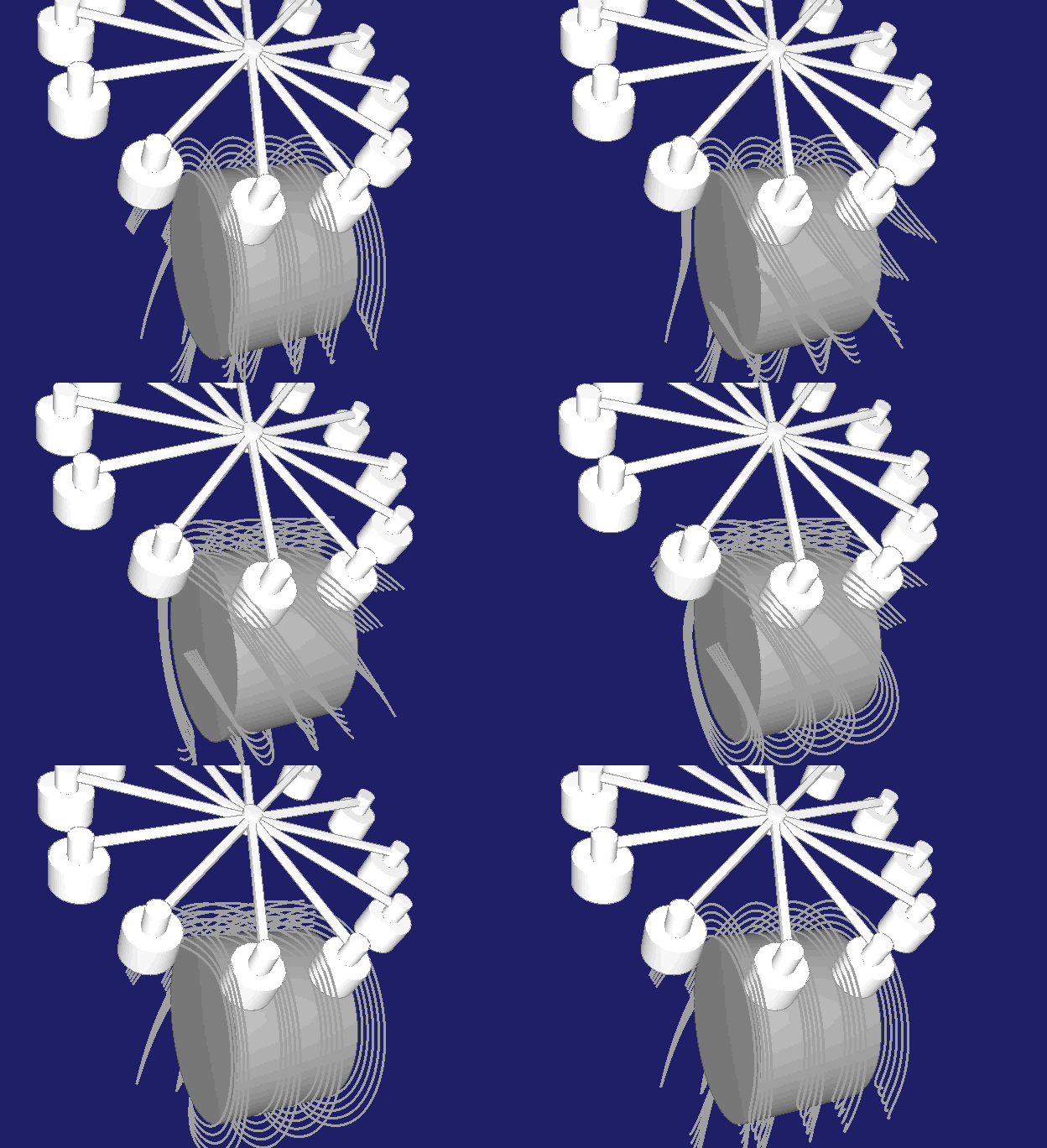
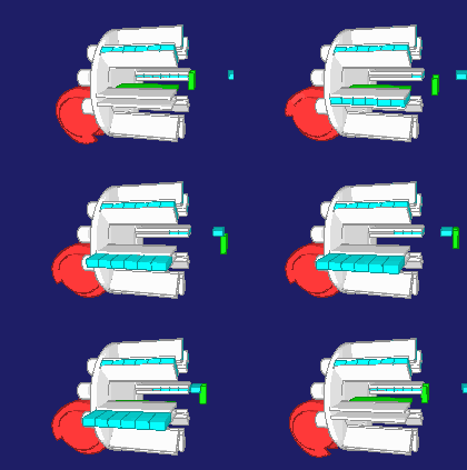
Cylindrical Indexing Cams, Barrel Cams
Cylindrical indexing cams are an application of cylindrical cams (barrel cams) and a special type of indexing gear. Often they are used in assembly machines for controlling the turntables that carry the articles. Indexing gears with cylindrical cams are powerful and offer high performance.
In case of cylindrical indexers, the output movement can be freely designed with jerk-free, smooth laws of motion. Therefore, with the same gear type, many other applications are possible.
The cylindrical index drives have the disadvantage over the globoidal indexing cam gears that the cam ridges become narrower on smaller cam diameters.
Skip to ...
- Variants
- Design
- Spreading
- Freecutting
- Roundings
- Chamfers
- Track concatenation
- NC Optimization
- Software
- Calculation service
To the homepage of Nolte NC-Kurventechnik GmbH
Variants
For barrel type indexing cam gears you will find different variants.
Groove or ridge in the middle
Indexing gears usually contain dwell phases in the movement. The follower may have any position in the dwell phase, but usually the rollers are arranged symmetrically in the dwell. Then there are two alternatives:
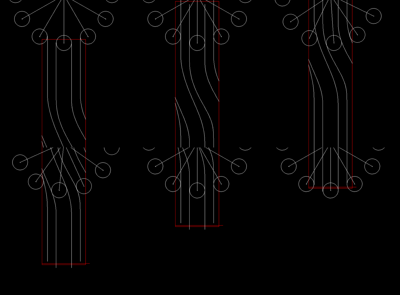
1.) Groove in the middle
Cylindrical indexing cam gear, 1 track, groove in the middle, in developed view:
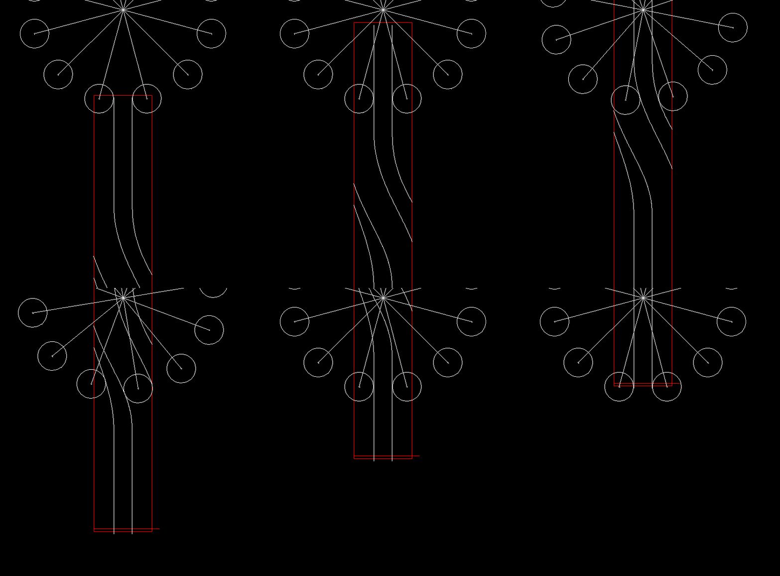
2.) Ridge (bulge) in the middle
Cylindrical indexing cam gear, 1 track, ridge in the middle, in developed view:
Unlike globoidal cams, you can not effectively optimize the backlash in barrel cams by changing the center distance.
Track Count
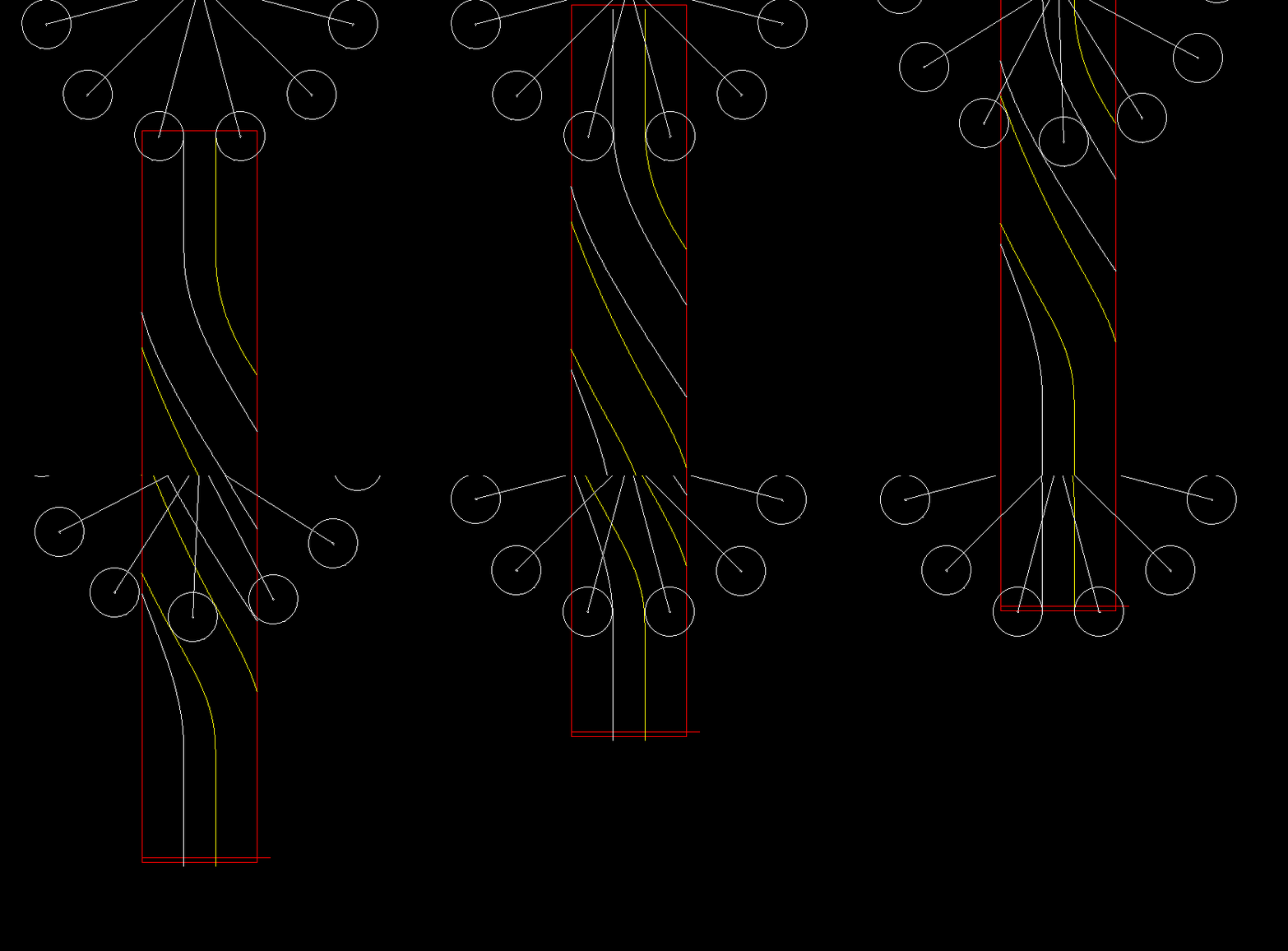
Cylindrical indexing cams also differ in the number of roller pitches that are crossed by the output wheel in one cycle. The cam will have a corresponding number of different tracks. For example, if you have 8 rollers on the follower wheel, corresponding to a pitch angle of 45 degrees, and the follower rotates by 90 degrees in one cam cycle, you will get 2 tracks on the cam. The individual tracks differ geometrically from each other and are produced one after the other.
The previous two animations show one-track cam gears.
Here is a two-track barrel cam indexer:
And finally an indexer with three tracks:
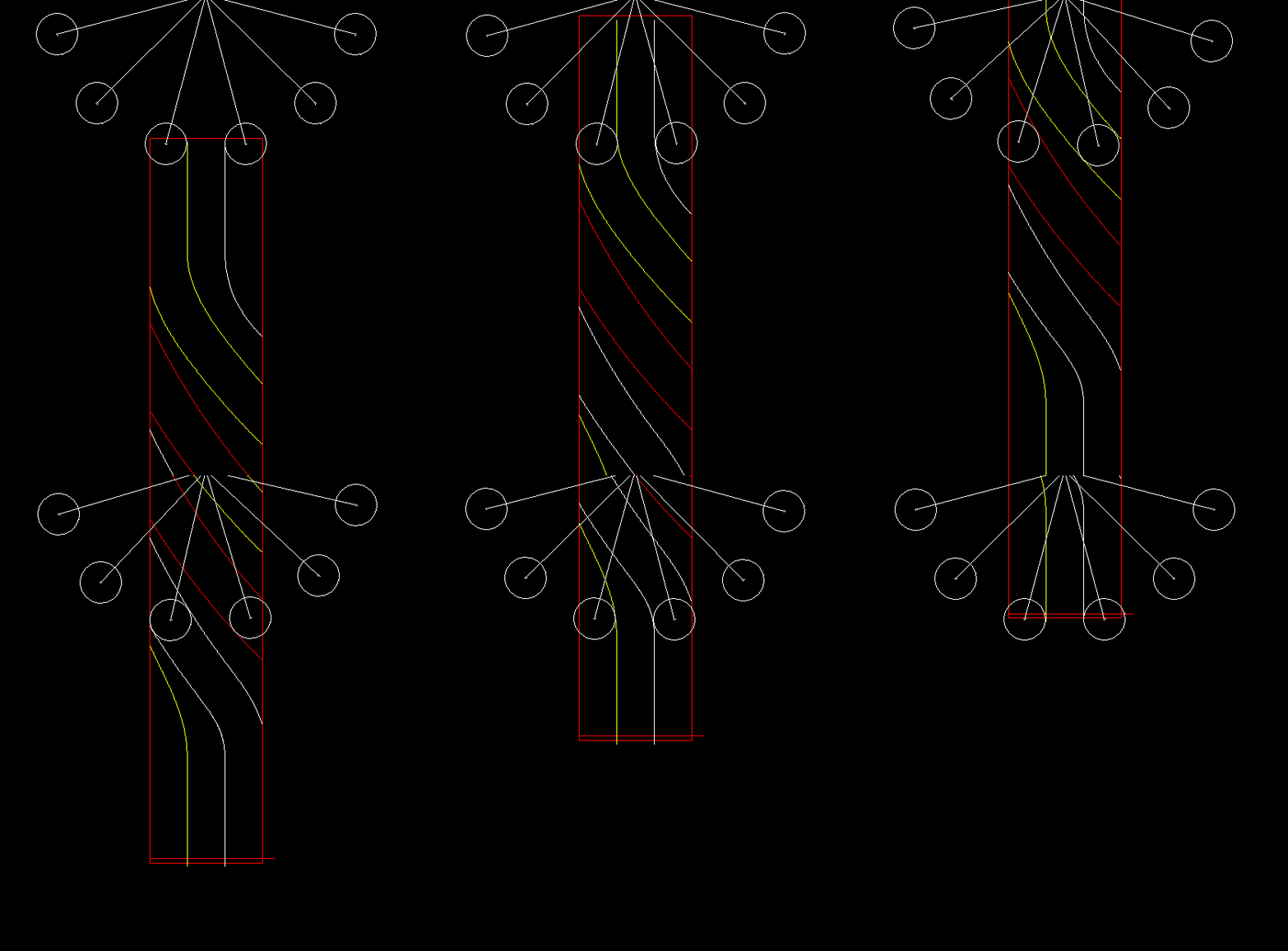
More tracks need more room, so that the ridges (the "walls" between the tracks) become narrower. These ridges must be thick enough along the full height of the cam flanks.
More tracks also means greater step angle, steeper cam flanks and worse transmission angle.
For multi-track indexing cam gears, therefore, motion laws with a large straight line insert are often used.
Movement type
Cylindrical indexing cam gears transform a uniform rotational movement into stepping movements on the output (roller star / turntable). Rotation and dwell phases alternate, and the rotations on the output always work in the same direction.
Compared with the parallel indexing cam gears, (type CF3), cylindrical indexers have the advantage that the output rotation may also run backwards to the same degree. Barrel type indexing cams thus enable oscillating rotations on the follower with a large angle of motion. In barrel cams with one or two rollers on the output lever, the swivel angle is limited to well below 180 degrees, in practice rather to less than 120 degrees, otherwise an unfavorable transmission angle would occur.
Cylindrical indexing cams, however, also allow for pilgrim stepping movements that progress by a multiple of the pitch angle in each cycle, but with reverse turns in between.
In addition, cylindrical indexing cams are also produced with constant gear ratio between drive and output. Their transfer function then is a straight line. With one gear stage large gearing ratios are possible. Such transmissions are usually controlled by servo drives. They act similar to worm gears, but have lower friction.
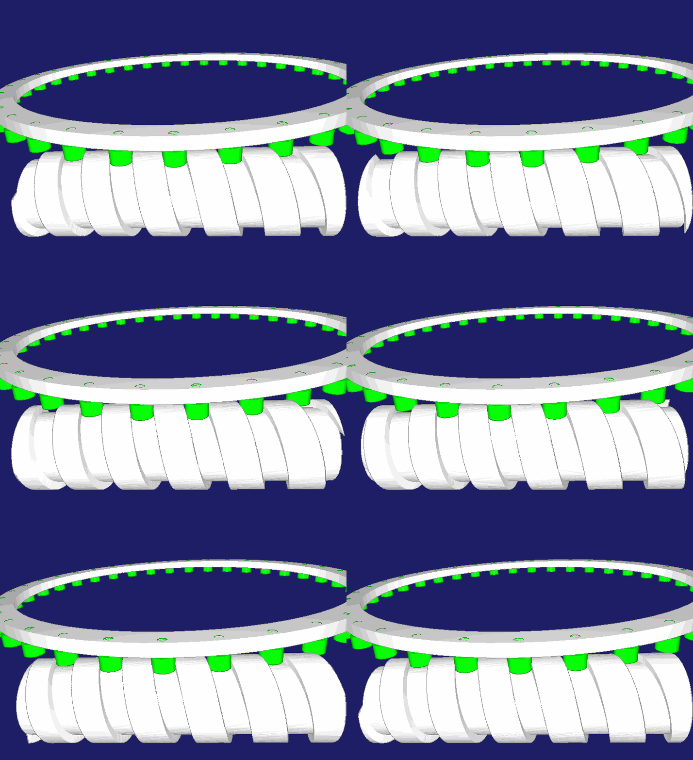
The kinematic structure of the cylinder cam gear offers great freedom of design for the output movements.
In addition to stepping movements, oscillating movements, constant gearing ratios and pilgrim steps, also quite general output movements are possible, even without dwells.
The software OPTIMUS MOTUS covers all these variants!
Cam Design
When configuring a cylindrical indexing cam gear, it is necessary to quickly state whether a particular gear can withstand the load at the desired speed, or vice versa, which gearbox size and design is required for a given durability, if such a gear can ever be made.
The customer wants to know if he can get a suitable gearbox for his movement task and at what price.
The supplier must decide at short notice and as well as possible whether he can supply the customer with an indexer for the task, and what size and design is required. Because he wants to offer his customer the most suitable and cheapest possible gear that can cope with the movement task.
The OPTIMUS MOTUS software offers a special indexing cam gear design for such examinations.
In a dialog box you enter the most important parameters for the calculation, eg center distance, cam width, follower pitch radius, roller number, crowning radius, dynamic load rating of the roller, indexing angle, cam angle for indexing, cam flank outside diameter, cam flank inside diameter, working cam diameter, moment of inertia, cycle speed.
OPTIMUS MOTUS carries out calculations and evaluates kinematically and dynamically whether the gearbox is executable and estimates the nominal life of the rollers and the cam.
It also takes into account that the load may be spread over several rollers!
In particular, you get the following results:
Coverage
Distance along the camd path over which several camd profiles have contact with rollers. At least this must be 0, because the follower otherwise has large backlash.
Ridge (bulge) thickness
Minimum width of the ridges between the cam flanks outside, inside and in the middle of the cam flanks. Too thin ridges do not carry the load. As a rule, the ridge thicknesses are smaller on the inner cam diameter than on the outer diameter in case of cylindrical cams.
Transmission angle
Here we consider the worst-case value of the transmission angle across all tracks. This minimum transmission angle evaluates the maximum slope of the cam. Where multiple rollers are engaged, it is not clear to what extent each roller carries loads due to the distribution of manufacturing deviations. So there might be a roller engaged with a slightly better transmission angle. 45 degrees is assumed to be good, 60 degrees a very good value for the transmission angle. In general, to get the worst occurring transmission angle closer to the optimum value of 90 degrees, you have to make the cam diameters larger.
Profile radius of curvature
The smallest radii of curvature in the convex areas of the cam profile are calculated on the outer case diameter, on the working diameter and on the smallest cam flank diameter. If values are less than 0 mm, there is an undercut. Then the cam edge cuts itself away, and on the real cam you see sharp edges in the cam flank. If the profile radius of curvature is greater than a few tenths of a mm on the effective diameter, the cam design can often be accepted. Many parameters affect the radius of curvature. OPTIMUS MOTUS automatically replaces undercut areas by roundings when exporting 3D data so that the cam grooves can be exported to the CAD.
Maximum roller force
The greatest force in the contact between cam and roller.
Maximum drive power
The required peak power at the drive in kilowatts.
Roller lifetime / durability
Very important is the nominal roller life, ie the lifetime statistically reached by 90% of all rolling bearings, without inclusion of operating factors. The roller wheel fails when only one roller is damaged. Therefore OPTIMUS MOTUS also calculates the nominal durability for all rollers together, also with a statistical failure rate of 10%.
Cam lifetime
With the help of the maximum occurring Hertzian pressure, it is estimated how long no pittings will occur if the cam flank is hardened to 60 HRC or 62 HRC. For heavily loaded cam flanks, these are common hardness values.
Maximum output speed
The highest angular velocity at the output in the indexing phase.
Maximum output acceleration
The highest angular acceleration at the output in the indexing phase. Furthermore, the software estimates which static load, which moment of inertia and which drive speed are reached, which minimum width the cam must have and which straight line proportion is required in the law of motion.
The calculation results are clearly arranged, as in this example:
Spreading
With a special "spread" function, you can eliminate or optimize the backlash in the cam gear.
Backlash is bad for transmissions especially at high speeds. In gearboxes with backlash, the output is not clearly positioned, the turntable can flutter during slack. Thus, the indexer would not fulfill its main task. Slack results in shocks in contact between cam and rollers and thus wear and noise.
In double cam discs slack is often eliminated or optimized by eccentric pins or other adjustments of the distance between the two roller centers to achieve the best possible running characteristics for the cam gear.
However, eccentric bolts can not be used with cylindrical indexing cams. To remove the backlash from the gearbox, the cam flanks are designed in a certain way with variable and optimizable allowance, so that they push the cam rollers away from each other or to each other. The camd paths are virtually "spread".
Barrel indexing cams consist of cam grooves (tracks). If one of the flanks has an allowance, the counter flank must be retracted to the same extent so that the roller still passes the groove. So spreading offsets the entire groove, but not everywhere by the same amount. The offset can work into both possible directions, so that the rollers can be pressed outwards and also inwards.
The spreading braces the rollers against each other. Larger oversizes and stiffer roller bearings increase the static clamping forces. The spread allowance should therefore be as small as possible. It just has to be enough to compensate for the expected production and assembly backlash.
An animation should illustrate the spreading.
It shows the same transmission as above, with constant gearing ratio, but with (very much exaggerated) spread of the cam flanks. It can be seen how theoretically the left and right rollers would penetrate the cam ridges. In practice, however, the cam flanks would push the rollers aside. Slack then has little chance.
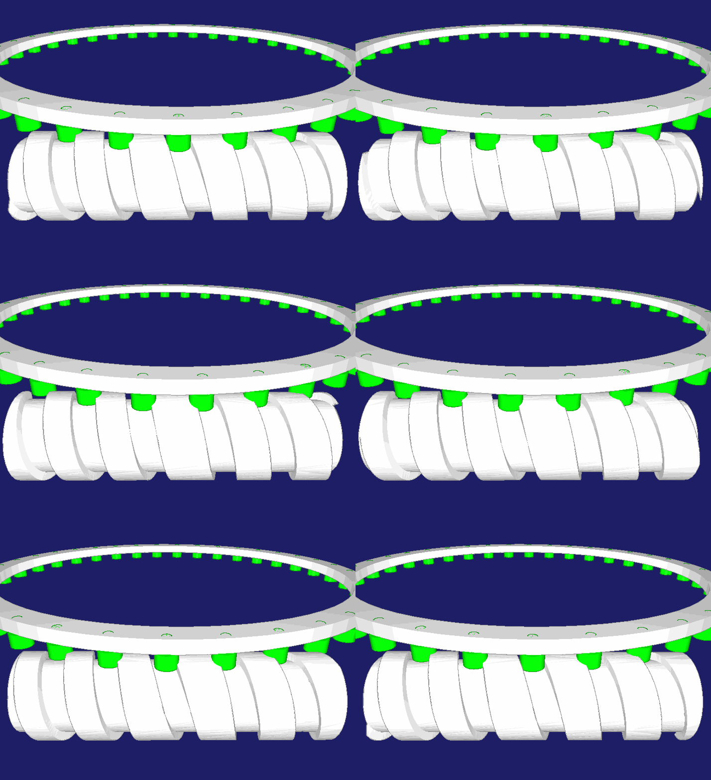
For globoidal indexing cams, the spreading function is used in the same way. Here you can see a 2D animation for a developed view.
When spreading cylinder indexing cams, you should also use the freecutting function.
Freecutting
Slight dimensional deviations are unavoidable when manufacturing and assembling cylindrical indexers. This affects the shape and position of the cam flank, but also important kinematic dimensions such as the center distance, the pitch radius of the roller centers, the pitch angle on the roller wheel, the roller diameter, etc.
Such deviations cause the rollers not to enter the cam exactly tangential to the cam flank, but to move in with a slight offset and so hit hard on the cam flank. Due to the spreading function, this scenario even results in theory.
Shocks of this type generate noise and wear and reduce the life of the cam rollers.
You can take back the cam flanks a little at the edges of the cam, to generate kind of an inlet funnel for the rollers. To avoid dynamic problems from the inlet funnel, we also provide for tangential transitions. The maximum amount of profile reductions and the width of the zones along the cam axis shall be determined in such a way that the maximum errors expected as a result of production and assembly are just compensated.
In practice, freecuts are sometimes applied manually with the file or the flex. This is time consuming and not ideal for the running characteristics of the cam.
Our OPTIMUS MOTUS software integrates the defined profile retractions directly into the exported NC data, so that no one needs a flex for the perfect entry of the rollers into the cam.
Freecutting is often combined with the spreading function.
An animation illustrates the profile reductions for cropping:
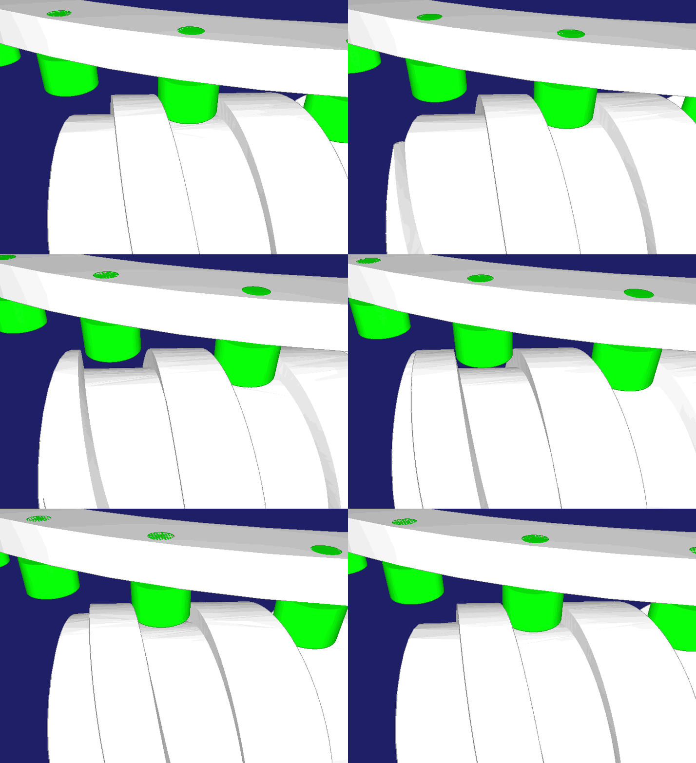
In globoidal indexers, the entry and exit areas are also cut free. Here you can see a corresponding 2D animation for the handling.
Roundings
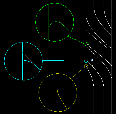
When cutting barrel cams, edges are created in the entry and exit areas of the cam grooves, which are often rounded in the workshop with the flex.
If required, the NC postprocessors of OPTIMUS MOTUS automatically insert NC blocks into the exported NC data in order to round off these edges programmatically.
The following image represents different types of fillets:
Chamfers
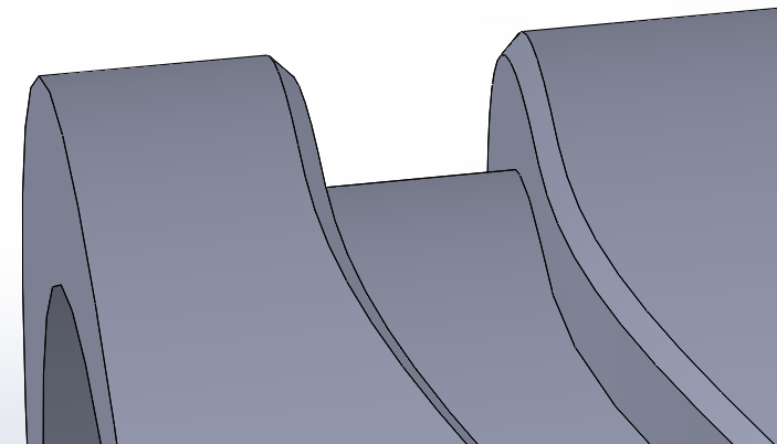
When milling cylinder cam grooves, sharp edges are created between the cam flanks and the outer case of the cam. Even such edges are often broken in the operation with file or Flex, which is time consuming.
On request, OPTIMUS MOTUS generates NC data for conic tools, which deburr the edges of the camd edges programmatically.
This allows you to achieve uniform chamfers with a defined width with little effort and reproducibly.
Track concatenation
For multi-track indexing cams, OPTIMUS MOTUS automatically concatenates the NC blocks of all tracks into one overall NC program.
NC Optimization
Cylindrical indexing cams are usually processed with four axes (XYZ + rotary table). If a finishing cutter (tool diameter = roller diameter) is always used for finishing, as we have often experienced in practice, high tooling costs arise.
The software OPTIMUS MOTUS considers a tool radius compensation for cylindrical cams and indexers and outputs NC data either for a tool diameter specified by the user or - by parameter programming - for variable tool diameters. The worker then enters the actual tool diameter on his CNC control.
This feature in OPTIMUS MOTUS reduces the tool costs considerably.
When milling a cylindrical cam flank with a standard tool diameter, too much material is left behind - even from the theory - and all the more, the greater the cam slope, the flank height and the difference between the tool and roller diameter.
We estimate these deviations to ensure the precision of cams cut with standard tools.
OPTIMUS MOTUS can numerically optimize the NC data with four or five controlled axis, in order to further reduce the remaining profile deviations.
With cylindrical indexing cams, the theoretical residual profile deviation can be reduced almost to 0.
To the homepage of Nolte NC-Kurventechnik GmbH
Start Mechanisms Kinematics CamDesign Indexing Servo+PLC MotionDesign Training Software Service CamCalculation Imprint PrivacyPolicy
Variants Evaluation Spreading Freecutting Fillets Chamfers TrackConcatenation NC-optimization
11/06/21
• Software OPTIMUS MOTUS ® /
DasNolte ®
• All types of Cam Calculations
• Performance Optimizations
• Trainings and consulting
• App and Software Development
• PLC Motion Software
Cams, Mechanisms, Motion Design. Faster Machines. Since 1965.
