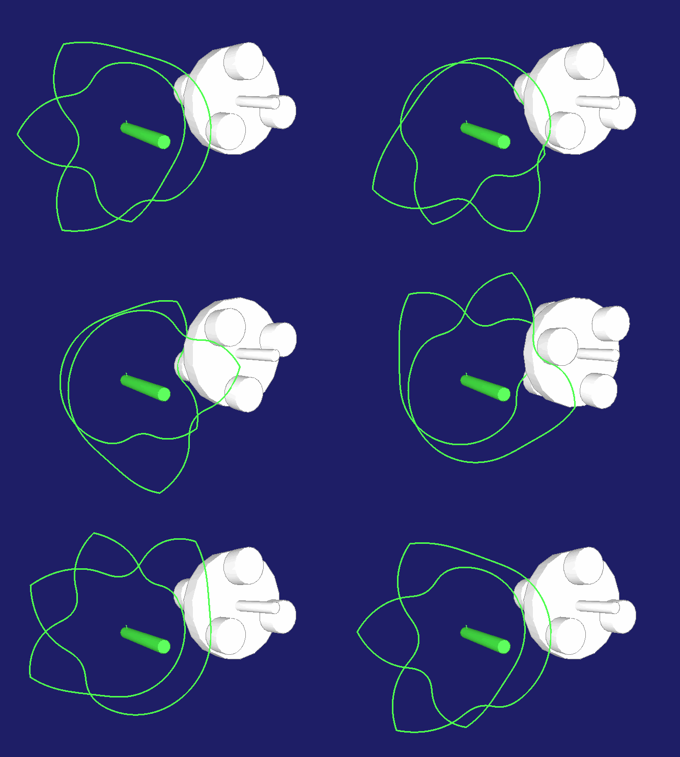
Parallel indexing cams, parallel cam gear, CF3 gearbox
Parallel indexing cam gears represent a special type of indexer and an application of planar cams.
Unlike the also very common globoidal and cylindrical indexing cam gears, parallel indexing cams have input and output shafts. Drive and output shaft must have a center distance greater than 0.
The arrangement is reminiscent of a spur gear. Spur gears are known for constant gear ratios. Spur gears can be calculated and produced for non-uniform transfer functions as non-circular gears. Even with non-circular gears, however, the slope of the transfer function must always be clearly different from 0. With spur gears, no stops on the output are possible at a constant drive speed.
However, this is what the parallel indexing cam drive offers: Step movements with indexing and dwell phase at the gearbox output with parallel axes.
Since the cams - as core components of the indexers - are planar cams, manufacturing them is simple compared to cylindrical or globoidal cams. Neither round table nor tool pivot axis are needed for the production. Only two axes X and Y need to be coordinated.
For comparison, an animation for a non-circular gear wheel pair (drive or input left, output or output right, gear wheels represented by their pitch curves):
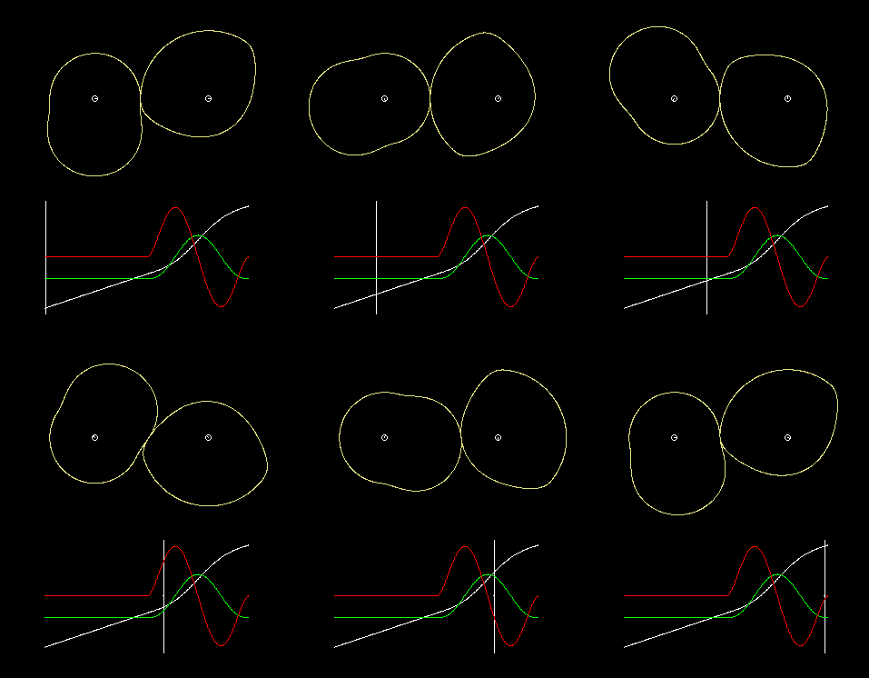
Parallel cam or CF3 transmissions have a fundamental disadvantage: in the dwell phase, due to the concept, the transmission angle is not good. The more rollers are distributed to the planes of the roller wheel, the worse the transmission angle becomes.
Skip to ...
To the homepage of Nolte NC-Kurventechnik GmbH
Variants
Parallel cams also work with inner cams, ie with inner rollers, as in the following animation:
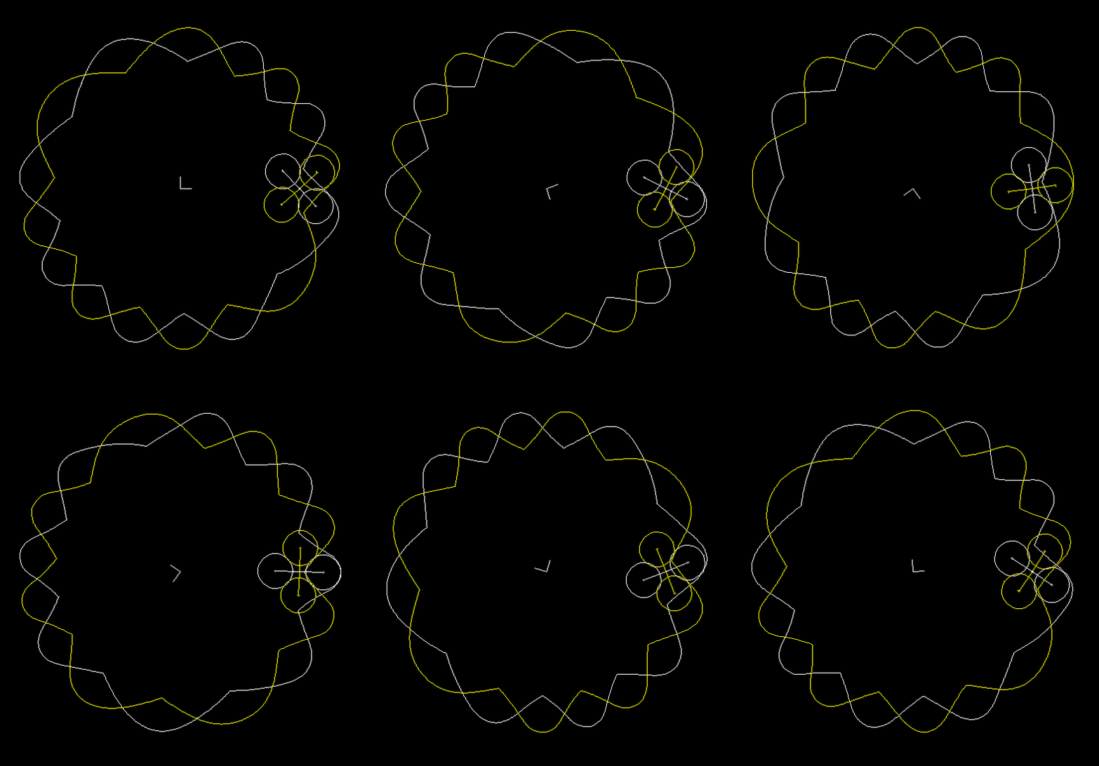
For parallel cams with outside cam profiles, the cam and the roller wheel rotate in opposite directions, in parallel cams with inside cam profiles essentially in the same direction. Reverse turns are possible, but only to very limited extent. Backward rotations further degrade the transmission angle, and at this point parallel cams do not have much reserve.
When kinematic reversal is applied, the cams may be fixed while the roller wheels rotate on a carousel:
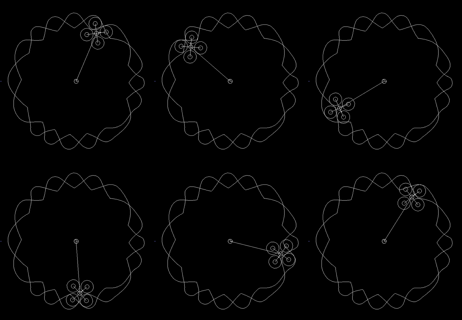
Such an arrangement is very well suited to achieve high performance in continuous operation with multiple samples, ie with multiple rotating followers on the same cam.
Normally, a parallel cam gear consists of two cam discs, and the rollers are all of the same diameter and evenly distributed on the roller wheel, on a uniform pitch diameter and in two planes. The roller rings of both planes are offset by half the pitch angle.
You can leave this standard case, however, for example to improve transmission angle or radius of curvature.
The following modifications are conceivable:
- 3 or more planes on the follower and correspondingly many cams
- different roller diameter
- different pitch diameter, also on the same roller plane
- different pitch angles between the rollers
It is important that the roller assembly pattern repeats after one turn of the cam. Otherwise there would be steps in the theoretical cam profiles. In addition, the number of cams must correspond to the number of roller levels. Basically, the standard arrangement is preferable because it is cheapest to manufacture and least susceptible to failure.
Here is an animation of a parallel cam gear with 3 levels:
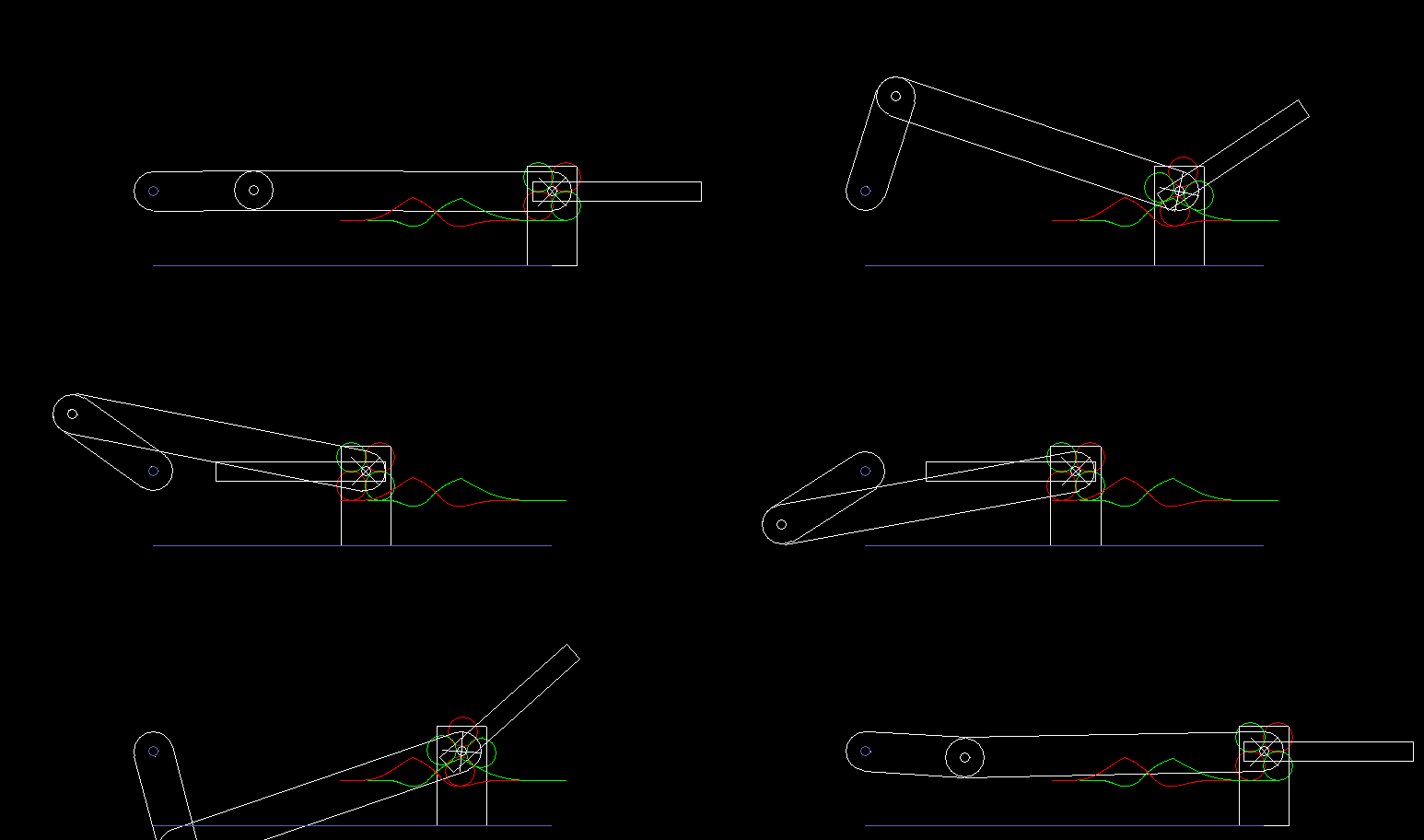
The following animation shows a transmission with linear drive of the parallel cam gear from the relative movement of the carriage relative to the frame. For the rotation of the crank (left) a constant angular velocity was given, and the 180 degree swinging movement of the flap was defined in a displacement plan with jerk-free laws of motion. The cam tracks have been calculated to compensate for the nonuniformity of the transfer function of the slider-crank drive.
In other words, the crank and flap rotations were given, and the cam calculation took the nonlinearity of the kinematics into account.
Undercutting
For cams you know about the problem of undercutting, when the cam flank cuts itself away because of excessive curvature of the roller center path and becomes sharp-edged. Undercutting is usually caused by great acceleration values at the output, but it always depends on the exact engagement conditions in each cam point.
The following image shows - marked with red circles - two points in a parallel cam gear with undercutting, which was caused by excessive acceleration:
In order to avoid this type of undercut, for example, the pitch circle diameter of the roller follower, the roller diameter or the acceleration in the movement diagram of the roller wheel rotation can be reduced.
For parallel cams another type of undercut is relevant, which arises due to impermissibly high speeds at the roller wheel.
When the follower becomes too fast and the roller overruns the cam at the point of engagement, you get loops that can not be produced in reality.
An image shows an example of such looping. The loops are marked in red. The magenta lines bridge the unusable parts of the cam profile. Here, an envelope cam of the loop would have to be assumed as cam profile. However, these loop profiles can not guide the follower safely.
The limiting case is that the roller at the lowest point of the camd path is stationary for a moment relative to the cam. The roller center path of the cam then has a sharp corner, and the cam profile has a fillet that corresponds to the roller radius.
A third picture shows the intended normal case: the roller center curves contain no loops and no peaks, but run in relation to the polar angle of the roller centers strictly monotone - without return areas or breakpoints - and have no intersections with themselves.
Incidentally, the cams in the last three pictures differ only in the maximum slope of the transfer function or, assuming the same cam speed, in the maximum angular velocity of the roller wheel.
In order to avoid loopings and edges, the straight line portion in the movement section is increased. If this is not enough, or if this leads to inadmissibly high acceleration values on the follower, the pitch circle diameter of the roller wheel is reduced.
Design
When designing an indexer gearbox, the main question is whether a selected gearbox size works with a given load and speed, and what durability can be expected. Alternatively, it is asked which gear unit reaches a certain service life at a defined load and number of cycles.
The user wants to know if an indexing cam gear is available for his step movement and how much it costs. The provider of the stepping gear wants - if possible directly on the phone - to give an immediate answer to this question.
The OPTIMUS MOTUS software offers a special design module for indexing cam drives. In a dialog box you enter the most important parameters, eg center distance, roller pitch radius, number of rollers, roller diameter, roller crowning radius, dynamic load rating of the roller, step angle, indexing angle, turntable mass moment of inertia, input speed.
OPTIMUS MOTUS checks the transmission and estimates the nominal life of rollers and cam.
Insbesondere werden folgende Werte ermittelt:
Coverage
Run length over which several rollers are engaged. If the value is less than 0, the follower is not guided safely.
Transmission angle
The smallest transmission angle evaluates the steepness of the cam tracks with respect to the engagement of the rollers. Although a minimum transmission angle of 45 degrees is generally recommended, with parallel cams this limit value can hardly be met, just because of their nature.
Profile radius of curvature
The smallest profile radius of curvature is defined by the smallest circle radius in the convex (outwardly camd) portions of the cam profile. Negative values indicate undercutting. In practice, usually only a few tenths of a mm are sufficient for an acceptable cam profile.
Maximum occurring roller force
The greatest force in contact between roller and cam.
Maximum drive power
The peak value of the drive power in kW.
Roller durability
The nominal roller life in hours is particularly interesting for the design. This lifetime is statistically reached by 90% of all bearings at the assumed loads and speeds, without considering operating factors. The whole roller wheel fails with a single roller, and the probability of failure in a given time increases with the number of rollers on the follower. Therefore, a nominal roller life for the roller wheel as a whole is also determined.
Cam durability
Cam flanks are often hardened to 60 HRC or 62 HRC when they are heavily loaded. OPTIMUS MOTUS estimates lifetime of the cam flank with regard to pittings.
Maximum output speed
The maximum angular velocity at the roller wheel during the indexing phase.
Maximum output acceleration
The maximum angular acceleration at the roller wheel during the indexing phase.
Furthermore, we estimate at which maximum static load, at which maximum mass moment of inertia and at which drive speed the gearbox can be operated, and which straight line component is required in the movement section.
The results are clearly arranged by OPTIMUS MOTUS. Here is a sample of such an evaluation:
Manufacturing
The production of parallel gear cams is not in itself more difficult than the production of other cams. However, a few special features should be noted.
A characteristic feature of parallel cams are the tips in the cam profiles. They correspond to the points of intersection of the profile tracks of the individual rollers on a roller wheel plane. The produced cam profile consists of the inner cam profile pieces. However, the maximum profile radii in the area of the tips are often so large that they would collide with the axis of the roller wheel. As long as sufficient coverage is left, you can cut away the tips to ensure the freedom of the cam under the roller wheel axis.
The following figure shows an example of such a tip reduction:
You see that the two yellow rollers guide the follower, although the tips of the corresponding yellow camd path have been cut off.
Everything that you manufacture and assemble in mechanical engineering is subject to tolerances. In the case of parallel cam transmissions, such deviations have a particularly unfavorable effect in two ways:
1.) If a roller does not run perfectly tangential on its cam profile, it will bump noisily and wearily into the profile tip or corner.
To avoid this, the cam in the outermost radii ranges is slightly retracted. This profile withdrawal itself consists of tangential transitions. In the following picture, the theoretical cam flank is shown in white and the retracted one in red. We exaggerated the profile withdrawal very much to make the effect visible.
2.) If the roller passes through the lowest point of the cam profile, the transmission angle at this point is 0 degrees. The roller can not pass any torques to the follower here. If the roller is mounted on the follower slightly too far outside due to tolerances, or if the cam profile was produced with a small allowance, the roller will clamp slightly between follower and cam. It then has to be pressed gently through the hollow in the cam profile. The roller "crackles" when the gear is running, which is not desirable.
Therefore, you retract the cam profile in the areas where the transmission angle is impermissibly bad:
The following figure illustrates the differences between the theoretically calculated camd path and the cam profile to be produced:
With our OPTIMUS MOTUS software we are optimally prepared for the calculation of parallel indexing cam gears and also take into account the technical details, to let the gearboxes run as fast, quietly and wear-resistant as possible.
We would like to calculate these cams for you!
To the homepage of Nolte NC-Kurventechnik GmbH
Start Mechanisms Kinematics CamDesign Indexing Servo+PLC MotionDesign Training Software Service CamCalculation Imprint PrivacyPolicy
11/06/21
• Software OPTIMUS MOTUS ® /
DasNolte ®
• All types of Cam Calculations
• Performance Optimizations
• Trainings and consulting
• App and Software Development
• PLC Motion Software
Cams, Mechanisms, Motion Design. Faster Machines. Since 1965.
