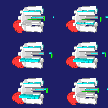
Globoidal cams
Globoidal cams are a common, but still very special design of cam gears. In practice, they are used almost exclusively in globoidal indexers, which are a standard device for generating step-wise motions. The lever following the cam by means of a roller oscillates for globoidal cams that are not indexing cams.
Globoidal cams are spatial (3D) cams. Input and output in globoidal cam gears rotate, and the axes of rotation of cam and follower are perpendicular to each other.
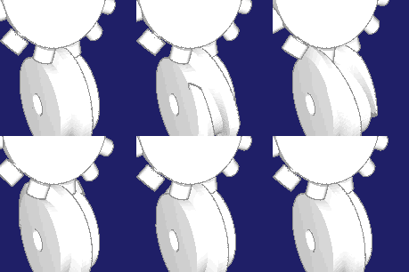
The special feature of globoidal cams is that the roller axis is located in the plane of movement of the rotating follower. In a globoidal indexer, the rollers form a "star" around the follower axis of rotation. For cam disks and cylindrical cams, in contrast, the roller axis is perpendicular to the follower plane of motion.
While for a cylindrical cam the cam tracks are introduced into a cylindrical case as a reference surface, for globoidal cams "tori" serve as reference surfaces. "Tori" is the plural of "Torus". A torus is the annular extrusion of a circular cross-section, as in a lifebuoy, a wheelbarrow tire or a donut.
In most cases only the inside part of the reference surface is used, towards the cam rotation axis. But it is also possible to use the outer side, so that the roller wheel or the lever moves within the cam flanks. Because of the star-shaped arrangement of the rollers cam ridges (bulges) look trapezoidal in globoidal cams, so are usually thicker on smaller cam diameters.
Advantages of globoidal cams:
- Cam bulges thicker at the bottom than at the top, high stiffness
- Compact and rigid construction
- High flywheel mass (advantage at constant drive speed)
Disadvantages of globoidal cams:
- High self-inertia (disadvantage with servo drives or emergency stop)
- Difficult to produce (only 5-axis machining), thus expensive
- Very complicated spatial geometry of the cam flank, must be taken into account during extrusions in 3D CAD
- Usually always sliding share in the contact between cam and roller, favors wear
The spatial geometry is even more complicated to handle in globoidal cams than in cylindrical cams.
We calculate globoidal cams with self-developed software for many years and are very familiar with it. We would like to assist you in the design of your globoidal cams and in the preparation of accurate NC data and CAD extrusions with our software OPTIMUS MOTUS and our consulting and calculation services.
Skip to ...
To the homepage of Nolte NC-Kurventechnik GmbH
Developed view
For globoidal cams, the developed view is not necessarily a common kind of presentation. The problem here is that the cam flanks must be handled in two directions, which always leads to distortions in the 2D presentation.
The torus as "carrier" of the cam flanks is first elongated to a cylinder assuming a reference diameter. This bends outward areas of the torus and stretches the inner ones, distorting the geometry of the cam flanks. Slopes and curvatures appear in the developed view different than in the spatial view of the original torus. Subsequently, the cylinder is either stretched or projected in the plane.
Unfortunately, a cam flank has a height, so tori in an entire diameter range must be handled ...
By the way, you have a similar problem if you want to show a world map distortion-free in the plane. You cannot do that without distortions!
To illustrate the process, here are some pictures:
First, the complete torus, which serves as a reference surface for the cam flanks:
Nearly all globoidal cam calculations refer only to the inner areas:
You unroll this "rim" to get a half-pipe. You use the reference diameter D (see picture below). The result is a half-pipe of length D•pi:
The reference diameter D is a medium value to approximately cover the cam diameter range that the cam flank utilizes.
The cylindrical groove is then either stretched out into the plane (alternative 1, left), or projected into the plane (alternative 2, right):
The advantage of the projection is that the width of the camd paths (along the axis of the cam) is maintained, but the disadvantage is that the camd paths are distorted once again for the presentation.
Despite the distortions that occur, we find the developed view practical and use it for the evaluation of cams. In most cases, the distortions are so small that it is still easy to see whether cam ridges are too thin, steepness too large and radii of curvature too small.
However, to take a close look you need a view on the spatial geometry of the cam flanks:
As with the cylindrical cams, gradients, curvatures and ridge thickness change along the contact line between the roller and the cam, ie with the height of the cam flank.
In the OPTIMUS MOTUS software, the cam flanks are calculated exactly on several reference tori. You get an exact 3D model of the roller space volume, which can be used for high-precision machining.
In particular, we also factor the tool radius compensation into the NC data for globoidal cams, so that the tool costs can be considerably reduced.
Coordinate systems
For the consideration of globoidal cams you need appropriate coordinate systems. They can be different in calculation, in CAD, in NC preparation and in the tooling machine. In practice, misunderstandings and mistakes easily arise. This applies above all to the signs of the axial directions in tooling machines.
When calculating a cam, we first generate metadata in a neutral format. With standardized or customized postprocessors we convert these data for production.
For the NC metadata we use the following coordinate system:
X = cam axis, main stroke direction
Y = center migration axis, perpendicular to X and Z
Z = height axis, perpendicular to X, in the plane of movement of the follower
A = cam angle or rotary table angle according to the left-hand rule (due to the kinematic reversal in the calculation)
B = swivel angle of the roller axis
The following animation shows these axes. Successively all axes move the tool.
Follow the coordinates X, Y, Z, A and B at the bottom of the screen!
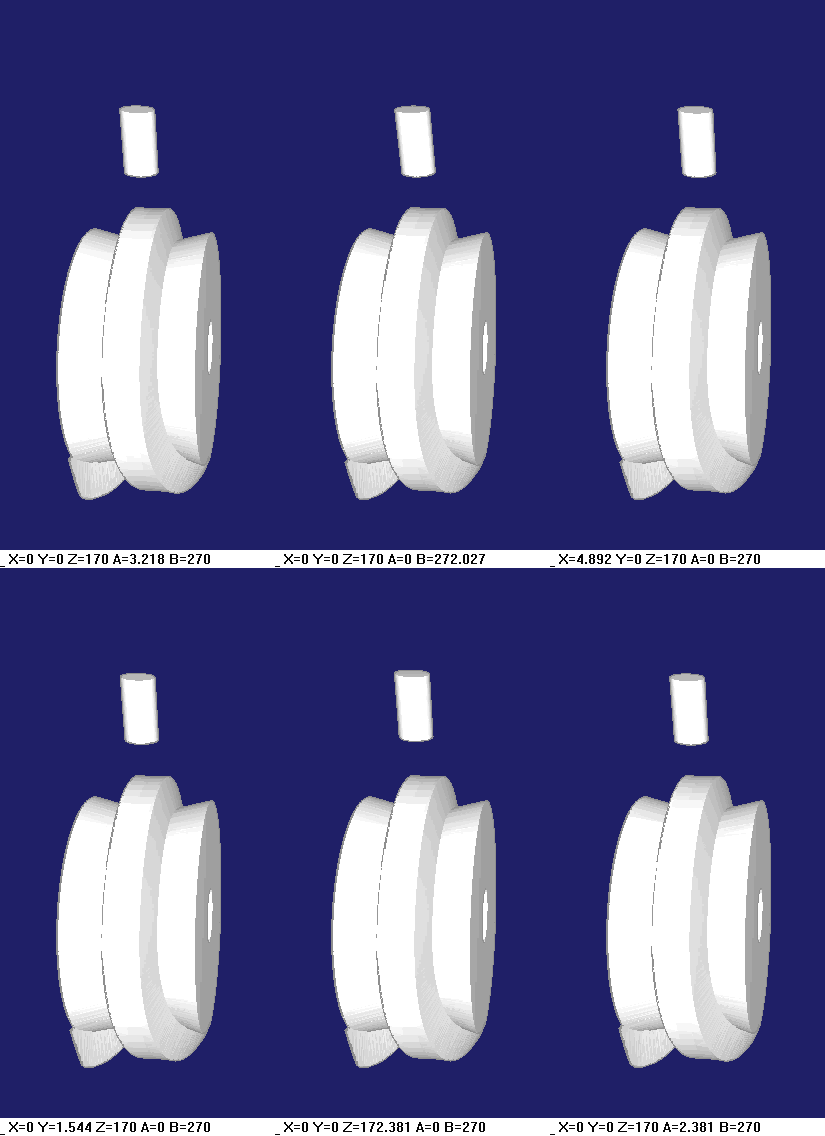
To find the transformation on a particular milling or grinding machine, let the machine move live in the different coordinate directions and note which axis on the machine is moving in which direction as the tool moves relative to the workpiece, like in the animation.
In the cutting machines two fundamentally different arrangements are to be distinguished. The axis designations A and B refer to the standard coordinate system used by us.
1.) The tool pivots according to the B-axis relative to the frame, and the cam rotates according to the A-axis relative to the frame. This is how it is shown in the animation.
2.) The tool does not pivot relative to the frame. Instead, the rotary-table that holds and rotates the cam pivots according to the B-axis relative to the frame.
In the second case, when transforming the coordinates for the NC control, not only axis designations and the signs must be adjusted, but also the coordinate values themselves must be converted. We develop customer-specific postprocessors for such NC coordinate transformations including geometric conversions like this.
When exporting CAD data, rotary table axis A and swivel axis B are not required. The globoidal camd paths are represented by 3D splines with X / Y / Z coordinates that refer to a cam coordinate system.
The X-axis of the cam coordinate system corresponds to the axis of rotation of the cam.
Y (perpendicular to X) is identical to the Y-axis of the NC metadata at phi = 0 (start of displacement plan).
Z is determined according to the right-hand rule: Z = X x Y.
The cam coordinate system for globoidal cams is the same as for cylindrical cams.
The origin for NC metadata and CAD data is on the cam rotation axis.
Manufacturing
Globoidal cams are cut on CNC machines with 5 synchronously controlled axes. The rotary table is needed to map the rotation of the cam around its axis. In addition, the pivoting movement of the tool must be mapped relative to the cam.
A simple but costly strategy is to make globoidal cams with tools that have the same diameter as the roller. But that is expensive for big rollers. Even with smaller rollers, you would always need a tool with nominal roller diameter with this strategy. Reground tools would no longer be used for finishing. In track cams you would also produce both flanks with different quality (reverse / synchronous), and where milling started, you would get a small disturbance, harming cam dynamics. For globoidal cams, CNC controls do not offer tool radius compensation to the best of our knowledge.
We therefore generate NC data for globoidal cams either directly for a defined tool diameter (including tool radius compensation), or we generate parametric NC programs with built-in tool radius compensation. With this parametric programming, the concrete tool diameter is entered on the CNC machine.
With the tool radius compensation of OPTIMUS MOTUS the tool procurement costs can be considerably reduced!
When cutting a globoidal cam flank with a tool not equal to the roller diameter in one cut, deviations occur on the profile. There is too much material left. These deviations are greater, the steeper the cam track is, the farther the profile point is away from the effective radius on the lever or roller wheel, and the greater the difference between the tool and roller diameter. The effect is similar to cylindrical cams.
It is expensive to cut cam flanks at many heights line by line with a convex tool, and longitudinal grooves are formed which impair the contact between the roller and the cam. This method theoretically generates more accurate cam geometry, but still is unattractive because of the effort and the surface quality disadvantage.
We estimate these profile deviations with the software OPTIMUS MOTUS for globoidal cams. So we determine for which tool diameter the deviations are not critical. Often the profile deviations are small, even with larger difference between roller and tool diameter.
For crowned cam rollers, the diameter at the edges is slightly smaller than in the middle, and very often the roller tapers along its axis faster than the profile error on the cam increases. In cross-section, the contact between roller and cam looks something like this:
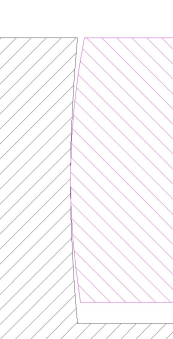
If the profile deviation increases too much along the roller, the roller runs only on the edge or clamps in a cam groove.
The OPTIMUS MOTUS software is able to numerically re-optimize NC data in order to minimize profile deviations.
Chamfers
When milling globoidal cam flanks, sharp edges remain between flank and outer case, which are often deburred with the flex or the file. The cost is high, and the hand-worked edges do not look nice.
Using special postprocessors in our OPTIMUS MOTUS software, we output NC data for tapered tools in order to deburr the globoidal cam flanks NC-controlled.
This results in uniform, clean chamfers with a constant width. Such cams look high quality, and you can keep the cost of deburring low.
CAD processing
For a correct CAD model of a globoidal cam, we calculate all cam flanks on several reference tori, ie at different heights of the cam flank, exactly and extrude a "roller trace volume" with these 3D curves. The roller trace volume is the track that the roller would leave when passing the cam.
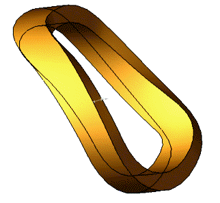
To obtain a solid model of the cam, subtract the roller trace volume from the cam blank.
Today, NC data are increasingly derived from solids, which are usually exchanged in STEP file format. Therefore, correct solid models of cams are very important for manufacturing today.
Generating cam solids is tricky. Simplified extrusions, for example, based only on the roller center path, look ok at first instance, but deviate from the correct shape of the cam flank.
Our OPTIMUS MOTUS software provides exact data for extruding solids ready for NC preparation.
Possible errors
The calculation and production of globoidal cams is definitely a topic for cam specialists.
If the calculation or the production does not master the peculiarities of the spatial geometry of the cam flanks, quickly unusable cams emerge. Then experience and analytic thinking are needed to find the errors.
With open globoidal cams, the roller always runs somehow across the cam flank, but the contact pattern between cam and roller is not correct when calculation or manufacturing errors have occurred. The cam might suffer from great wear, and the transmission function of the cam gear is corrupted. The cam gear would not do what it should. Open globoidal cams are relatively rare in practice.
Globoidal groove cams or double cams, especially indexing cams, will probably clamp in case of failure.
The rule for globoidal cams: calculate, manufacture and assemble correctly!
If you ever have problems with globoidal cams, the following checklist of potential errors might help:
- Calculated with incorrect kinematic dimensions
- Eccentric bolts used, but not included in the calculation
- Tool diameter too small for slope, flank height and roller diameter
- Assumed wrong basic kinematics of the machine tool
- Coordinates are not transformed correctly, especially the center migration axis
- No correct equidistant calculated, but NC data shifted only parallel to the axis
- Spatial geometry of the contact roller / cam is not considered correctly
- Wrong extrusion type used in CAD
- 3D curves for extruding the roller trace volume not determined correctly
- Rotary table has backlash
Special designs
With our OPTIMUS MOTUS software we also calculate special types of globoidal cam gears.
For example, one can crimp the rollers on the roller wheel of an indexing gear, so that the angle between the roller rotation axis and the follower rotation axis is not exactly 90 degrees, but between 0 degrees and 90 degrees.
Or you optimize the contact between roller and cam by making the camd track itself crowned:
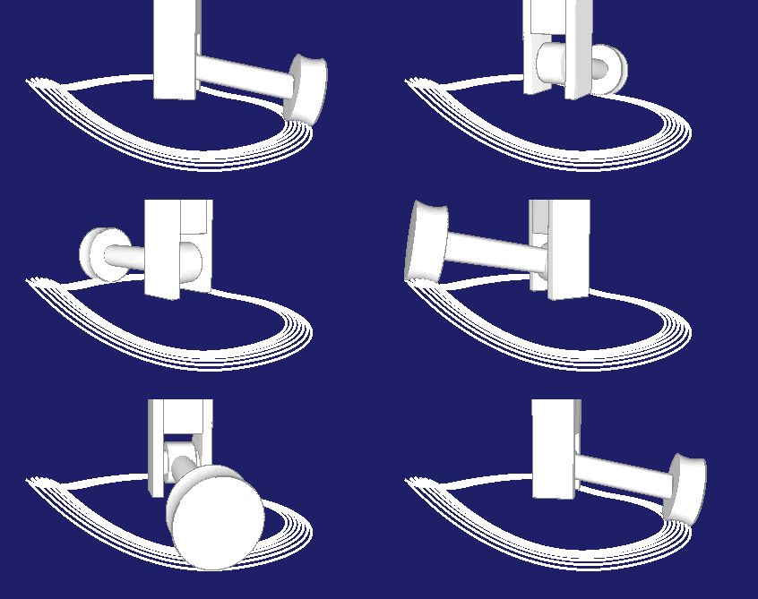
The roller case may then be made less concave, or even cylindrical.
The plane in which the roller wheel or the levers rotate can be tilted relative to the cam axis of rotation:
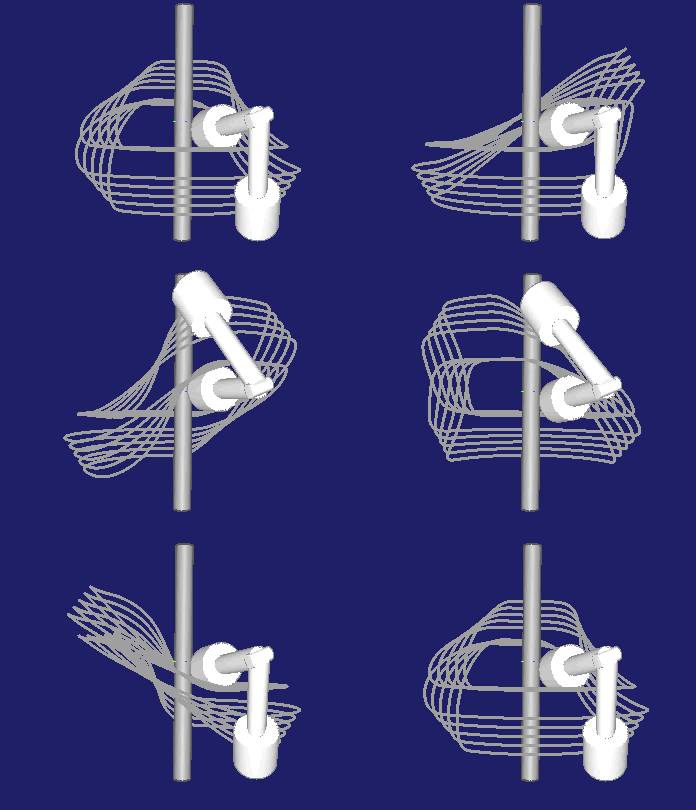
For general 3D cam calculations with our OPTIMUS MOTUS software
- the spatial movement of the cam
- the spatial movement of the rollers
- the crowning radius of the rollers
- and the tapering of the roller
may be freely set, so that the engineer may be very creative in his design of cam gears.
OPTIMUS MOTUS will also provide data for CAD modeling and NC machining in special cases.
To the homepage of Nolte NC-Kurventechnik GmbH
Start Mechanisms Kinematics CamDesign Indexing Training Servo+PLC MotionDesign Software Service CamCalculation Imprint PrivacyPolicy
DevelopedView Coordinates Cutting Chamfers CAD-Data Faults Special
11/06/21
• Software OPTIMUS MOTUS ® /
DasNolte ®
• All types of Cam Calculations
• Performance Optimizations
• Trainings and consulting
• App and Software Development
• PLC Motion Software
Cams, Mechanisms, Motion Design. Faster Machines. Since 1965.
