Motion design
Motion design means planning and fine tuning of movements in machines. This has been our core topic for over 45 years.
Motion design makes machines faster, quieter, more energy efficient and available, with the same manufacturing costs.
Motion design goes far beyond the simple application of fixed laws of motion (eg, 5th order polynomial or modified sine). Rather, "motion design" refers to a comprehensive optimization process in which the movements are designed in detail in such a way that the optimization goals are achieved in the best possible way. In particular, the characteristic shape of a law of motion is also redesigned if it helps. And we also optimize movements with numerical methods when it matters.
Typically you aim for high machine speed , but often you try to use small servomotors, gearboxes and converters to reduce costs, or you aim for high cam and roller lifetimes or low dynamic forces on the frame. All combinations of criteria are possible.
The better the motion design, the more powerful the machines. And in the competitive situation, it just depends on the last percentage points to win the contract for yourself. This applies equally to classic cam-controlled systems as well as to flexible concepts with servo-controls.
Motion design introduces a new quality into your machines and gets them to the next level.
Motion design is a must-have for manufacturers of machines where speed, smoothness, reproducibility and availability play a role.
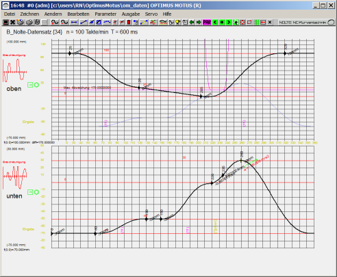
Our software OPTIMUS MOTUS offers in a graphical editor extremely versatile and efficient methods to dynamically optimize movements.
Benefit from our more than 45 years of experience and our constant push in this area!
We support you with consulting, motion design service and specialized software.
In addition, we pass on our know-how in motion design in seminars. In doing so, we also take up your concrete projects if you like.
Skip to ...
- Examples
- General
- Motion laws
- Range extension
- Collision optimization
- Energetic optimization
- HS Profiles
- Cubic Splines
- Software
- Calculation
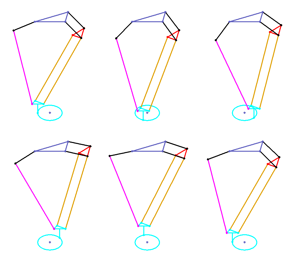
Practical example: Delta robot for pick & place or guiding movement
- Specify the trajectory with overlaps in X / Y
- Consider the nonlinearity of the mechanism
- Optimize accelerations and load of both motor-gearbox combinations
Aims:
- Best possible utilization of the drives
- Maximize cycle speed
- Avoid vibrations on the gripper with smooth movements
Practical example: Collecting wheel with rake in a packaging machine
A servo motor with gearbox drives a mechanical indexing cam that rotates collecting wheel. A rake (in the animation displayed as a green finger) pushes individual items into the collection wheel. Between two items, the collecting wheel rotates by one pitch.
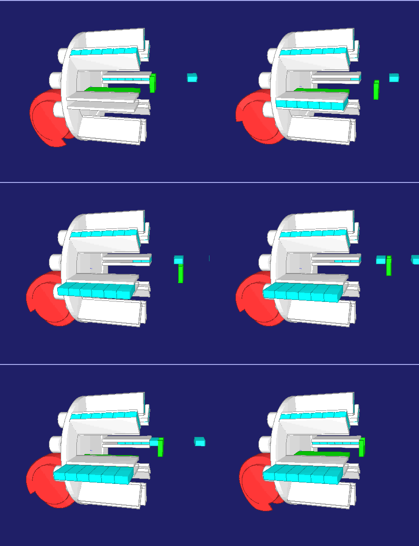
Only 45 milliseconds are allowed for the indexing movement!
Due to the combination of servo and mechanical cam, the drive loads from self-inertia (motor + gearbox) and from load inertia (collecting wheel) apply at different times so that the machine speed can be increased.
Accelerations, forces and torques are reduced by simulation and collision analysis.
Practical example: Device for stacking books
- 10 synchronous servo axes
- Wide variety of formats and stacking options
- Optimal motion design with jerk-free motion laws for all format variants with consideration of collisions
Aim:
Maximize number of cycles per minute for all format variants, optimal utilization of mechanics for all formats
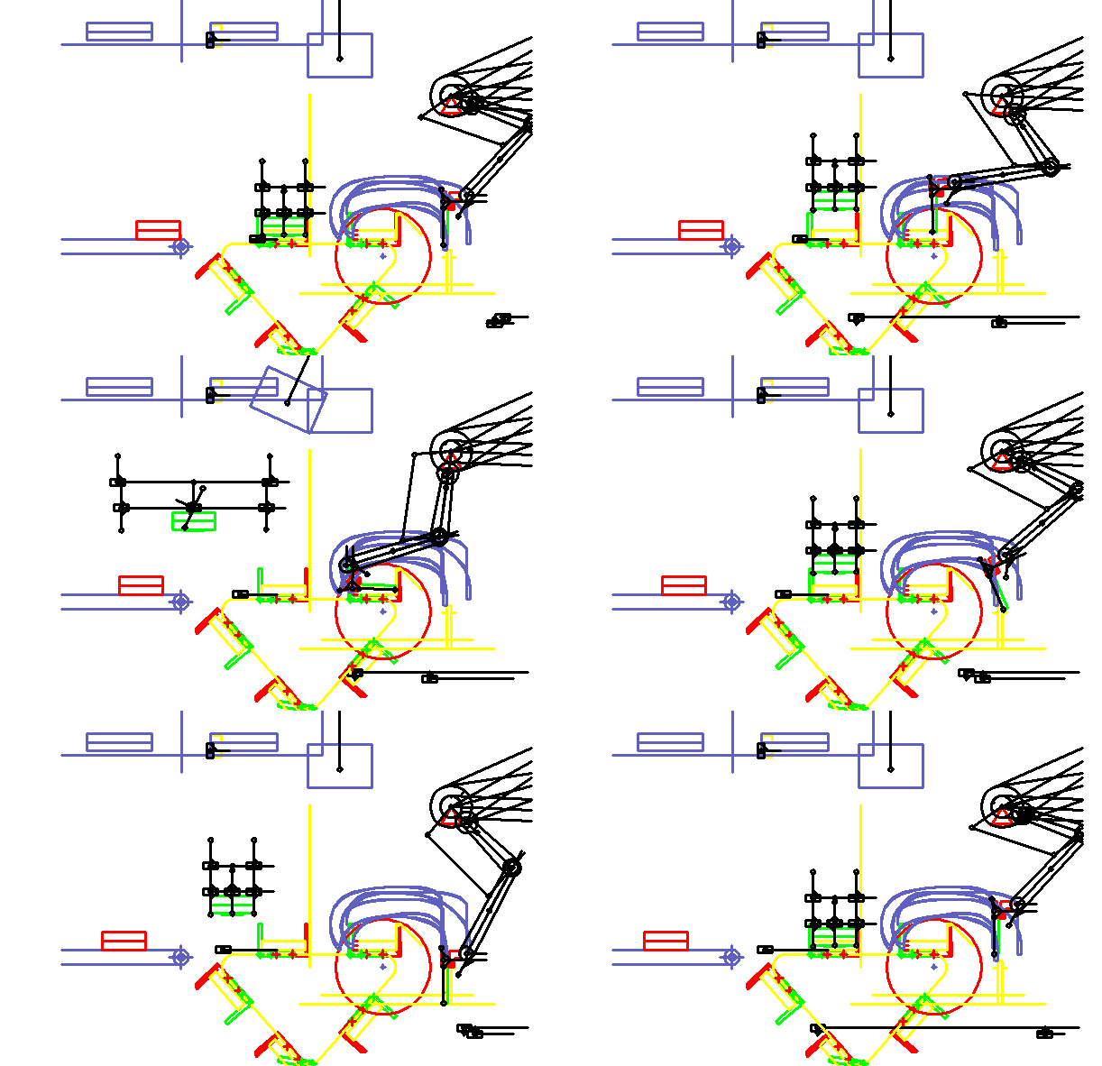
Note: We already created this animation in 1998. We have been dealing with the dynamic optimization of complex motion control systems with servo drives as a function of format parameters for more than 20 years!
Practical example: Pick & Place with 2 frame-mounted servo drives and belt drive
A gantry kinematics with two fixed drives and belts moves a gripper to assemble components.
- Vibrations due to the elasticity of the belt and lamellar articles themselves would hinder the insertion of the articles.
- Specially designed, smooth movements reduce vibration excitation and allow higher cycle rates.
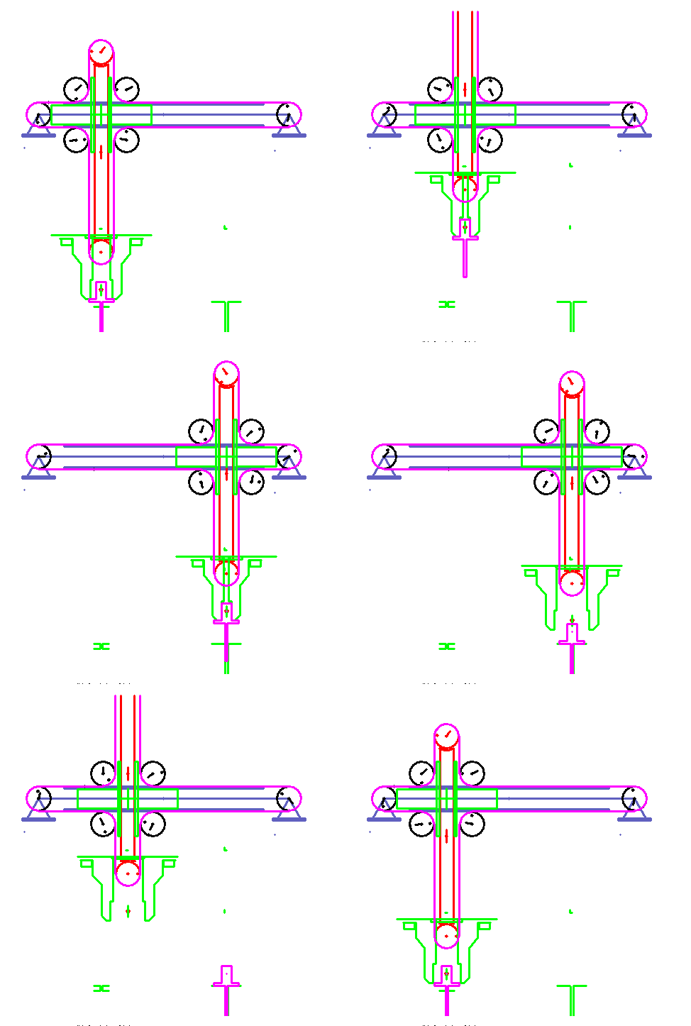
Example of this mechanic: Reduction of the acceleration from 126 m/s2 down to only 17 m/s2.
Practical example: Belt transport for chocolate bars
Practical example: Belt transport for chocolate bars.
Chocolate bars are fed with servo tapes from a casting machine to the subsequent packaging machine.
At the same time the chocolate bars are brought to a constant distance by offset movements.
To reach the required speed the tape accelerations must be minimized to prevent articles from slipping due to the low friction.

Practical example: Anti-slosh movement during the transport of liquids
Article transport with servo and chain in a filling machine (cups or bottles).
Approach 1 with conventional motion design (eg modified sine or polynomial 5th degree):
The containers vibrate themselves, or the liquid in the containers sloshes with very low natural frequency.
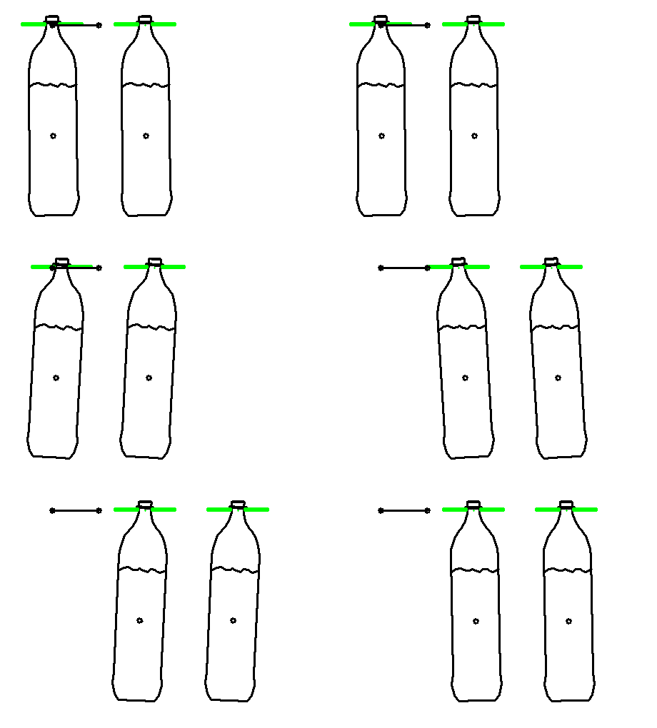
Problem:
With "normal" movements (jerk-free, polynomial 5th degree or similar), the natural vibrations can not be reduced sufficiently.
Approach 2: special motion design for low natural frequency:
With two special methods of motion design for very low natural frequencies, we can largely or completely eliminate the resulting vibrations.
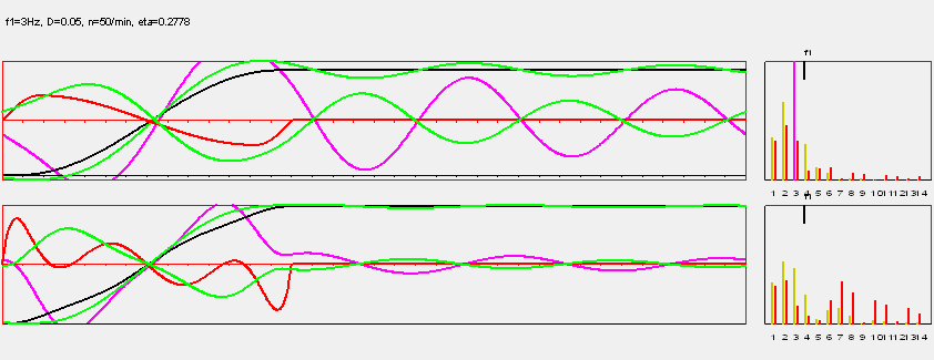
The upper diagram shows in black the movement specified by the indexing gear or the servo with the well-known and widely used Modified Sine motion law, which is still jerk-free. Magenta colors show how the bottle respectively the liquid reacts to it. By the way, the polynomial of degree 5 would look almost exactly the same.
The lower diagram shows the optimized motion according to the first special method. In black, the indexing motion of the servo or cam gear is displayed again, magenta the reaction of the liquid. The amplitude of the after-acting oscillation in the dwell phase has already dropped by almost 80%.
With a further algorithm developed by us, which also takes damping into account, we can also eliminate these residual vibrations.
The movement looks like this:
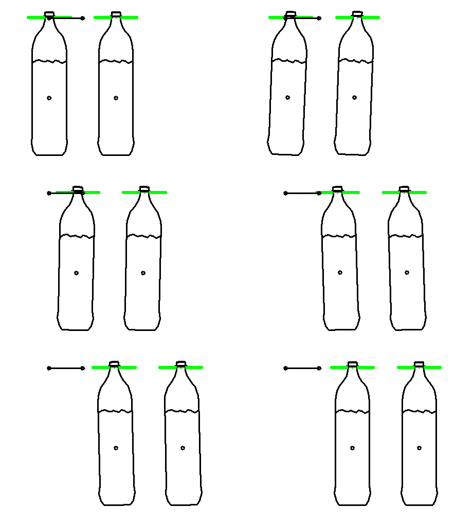
Durch den speziellen Ansatz kann das Nachschwingen der Flaschen bzw. der Flüssigkeit mit der Eigenfrequenz unterbunden werden.
Conclusion: Motion design …
- makes machines faster
- avoids downtime by reducing disturbing vibrations
- extends the life of cam, rollers and other components
- allows smaller and cheaper drives
- saves energy
Let us assist you with motion design to make your machines faster, more efficient, quieter and more economical!
General
The optimal motion design depends very much on the respective task. In general, cams and servo drives are dynamically optimized for maximum performance.
Performance means
- high cycle speeds
- low wear
- precise processing of the product
- quiet running
As a rule, optimizing one of these four criteria requires the improvement of the other three.
Motion optimization means finding the best possible compromise for the following and possibly further criteria:
- Acceleration maxima
- Acceleration curve shape
- Jerk function
- Vibration excitation
- Maximum drive torque
- Shapeof the dynamic torque
- Effective drive torque
- Rack forces
- Cam durability
- Roller durability
- Low energy turnover
There is no absolutely best motion law and no absolutely best motion design. The quality of a motion design can only be evaluated in relation to a specific mechanism with certain dynamic properties. For the fixed mechanism, therefore, it must be determined how the individual evaluation criteria should be weighted within the scope of motion optimization. For this weighting it is often helpful to have some experience with the dynamic properties of your machines and with motion optimization in general.
We optimize movements with the following measures:
- Motion law selection and design
- Turning point shift
- Boundary value adjustment
- Design of general sinusoidal combinations
- Design of general polynomials
- Design of general polynomial splines
- Design and numerical optimization of HS profiles
- Range extension
- Dynamically balanced distribution of transitional periods
- Collision optimization
- Numerical optimization of the motion diagram parameters
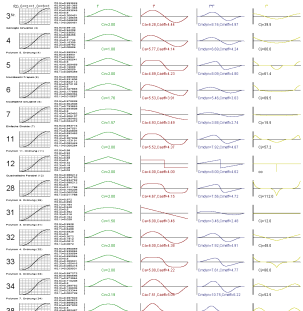
By appropriate choice of motion laws you create the basis for the optimization, because they set different weightings in the individual evaluation criteria. In this case, the characteristic form of the motion law can be changed or completely redesigned, if it is advantageous.
The inflection point shift emphasizes start or end of a movement and shifts the inside of the transition forward or backward in time.
The picture shows on the left a symmetrical law of motion with lambda = 0.5, on the right an asymmetrical law with lambda = 0.3:
Boundary value adjustments keep the speed, acceleration and possibly further derivatives in the transition points between the sections steady.
General sine combination , general polynomials, general polynomial splines and HS profiles are all very powerful approaches for adapting the motions to the dynamic properties of the mechanisms. With these methods you get the decisive percentage of performance!
The range extension extends movement sections beyond the theoretically provided time frame so that competing movements overlap within given tolerances. It is important to distribute the interdependent movement segments in such a way that all individual mechanisms ("axes") in comparison and each individual mechanism is dynamically equivalent over the cycle. The burden should be balanced overall. This sounds trivial, but you need powerful mechanism software to check the distribution of loads over time and across the axes. Estimating the best distribution is virtually impossible. Displacement plans that have been set up only by experience or intuition are often far from being balanced in practice. In such cases there is always a lot of potential to increase the machine speed with simple measures.
Collision optimization is a very effective means of motion optimization. Collision optimization means dynamic optimization with collision check. Parallel to the optimization of the displacement diagram, the resulting motion sequence is graphically simulated. Attempts are made to avoid the collisions in the sequence of movements as short as permissible, while distributing the dynamic loads evenly across all individual drives. Finally, all individual drives should reach the same maximum cycle speed.
The collision optimization is very effective with low effort. It has an optimal price-performance ratio for the machine developer. In practical applications we have often achieved more than 30% increase in machine speed with collision optimization. With collision optimization we have a lot and many years of experience. Here is an example from 1996.
Motion plans with our OPTIMUS MOTUS software may be parametric, and the parameters can be numerically optimized to any target function. That's the ultimate way to optimize your motion.
The movement in the following picture was numerically optimized according to a special algorithm in order to comply with the specified tolerance channel with minimal acceleration.
Looks a bit like the driving line of a racer, right?
Motion design is a holistic approach to dynamically design motion diagrams.
The aim is to make optimum use of the mechanisms and drives in order to achieve the highest possible performance.
Range expansion
Range extension is a technique for reducing dynamic loads in cam and servo drives within motion sections.
Mostly, range extension is used on dwell-to-dwell movement sections. But it can be applied on all motion sections.
When extending sections you take advantage of the fact that the path function progresses very slowly near the edges of a jerk-free motion section, so that a relatively long time elapses until a certain path builds up. Secondly, it makes good use of the fact that the travel end positions in motion segments only have to be maintained with a certain accuracy, but not up to the eighth decimal.
Procedure for symmetrical laws of motion:
1. Determine the actually used time angle range phi_original_nutz in the motion portion of the original length phi_original. (see sketch)
2. Calculate the new effective length: phi_neu_gesamt = phi_original2 / phi_original_nutz
In asymmetrical motion law sections, the time angle shifts of the left and right boundary positions are different!
Example:
In a movement section over 100 mm stroke at 120 degrees time angle, the motion law "Modified Sine" is used. However, the end positions do not have to be met exactly, but only with 0.1 mm accuracy.
From the path table for the movement section shows that 0.1 mm path are reached after about 5.3 degrees time angle. 99.9 mm way are reached after about 114.7 degrees time angle:
phi [deg] s [mm]
0.0 0.000
0.5 0.000
1.0 0.001
1.5 0.002
2.0 0.005
2.5 0.010
3.0 0.018
3.5 0.029
4.0 0.043
4.5 0.060
5.0 0.083
5.5 0.110
6.0 0.142
6.5 0.180
7.0 0.224
...
113.0 99.776
113.5 99.820
114.0 99.858
114.5 99.890
115.0 99.917
115.5 99.940
...
Between 0.1 mm travel and 99.9 mm travel (ie between the two tolerated boundary positions) there is a time angle difference of 109.4 degrees (instead of theoretically 120 degrees with zero tolerance). The entire motion section of 120 degrees long so far can now be stretched in time so that the 109.4 degrees time angle become 120 degrees time angle. The scaling factor on the time axis phi is thus 120 / 109.4.
The extended time angle range for the movement section is thus
phi_neu_gesamt = 120 • (120 / 109.4) = 131.6 deg
By taking advantage of the usually small tolerance of 0.1 mm, the maximum speed is reduced by 9%, the acceleration and thus dynamic forces by 17% and the dynamic drive torque by 24%!
HS Profiles
HS profiles are a special type of motion design for periodic mechanisms with cams or servo drives. "HS" stands for "Harmonic Synthesis" and means that movements are designed as a Fourier series, by superposition of sine functions with respective amplitudes and phase shifts. HS profiles are especially used for high-speed mechanisms that are susceptible to natural vibration.
HS profiles refer to the entire cycle of the periodically operating machine, not to a single motion section.
When calculating cams, the desired movement is usually specified on the output. The cam profiles are calculated from this purely kinematically, without consideration of elasticity.
But mechanisms are always elastic. The kinematic basic motion is therefore always superimposed by natural oscillations. Often, the natural frequencies change little during one cycle and can be considered constant. At a correspondingly high number of cycles or a higher
tuning ratio = working frequency / natural frequency
the superimposed natural oscillations become so relevant that the function of the mechanism is impaired.
It is not possible to specify a fixed limit for the allowable tuning ratio up to which the superimposed natural oscillations are harmless, because the excitation of the natural vibrations depends very much on the motion design, and the accuracy requirements are different.
However, one can roughly estimate the superimposed natural oscillations with the aid of single-mass models or determine them more precisely by simulation with MBS programs.
The aim of using an HS profile is to minimize the dynamic deviations from the desired movement at operating speed. The idea is to stimulate the mechanism in the range of natural frequencies as little as possible, since an excitation in this area falsifies the kinematically given movement strongly. Therefore, the motion is composed of a few harmonics whose highest frequency remains well below the lowest natural frequency of the mechanism.
The k-th harmonic is a sine function with the frequency k ● cycle frequency.
The resulting movement at the output is composed of the stimulating movement of the cam and the superimposed natural vibrations. This resulting motion should be as close as possible to the desired motion for the output at operating speed.
The following two approaches are particularly important in the application of HS profiles:
Approach 1:
Specification of a motion diagram and use of the first N harmonics from the Fourier analysis of a motion diagram, which is usually defined in sections:
The number N of harmonics to be considered can be chosen so that the deviation of the resulting movement at the output from the desired movement becomes minimal.
If too few harmonics are used, the kinematic deviation due to the HS profile is very large, so that the mechanism does not work properly even at low speed.
If there are too many harmonics, the natural oscillations are already ignited.
Approach 2:
Specification of tolerance hoses for the resulting output motion and determination of the HS profile with numerical optimization.
In this technique, tolerance channels are specified, which should be complied with both by the kinematic motion specification (the excitation) and by the reaction on the output, which is estimated on the basis of a single-mass model.
A specially designed numerical method searches for an HS profile with a given number of harmonics that complies with these tolerance channels and also optimizes a linear objective function, such as the sum of the amplitudes of the harmonics.
This very powerful method uses very few harmonics to maintain the tolerance channels, so that the generated motion profiles stimulate natural oscillations of disturbing size only at high cycle times.
Both approaches are implemented in the mechanism software OPTIMUS MOTUS (R).
Cubic splines
The cubic spline interpolation is actually not one of the "design" methods for movements. However, it is of great importance if you want to map movements smoothly, which are defined by tables with many interpolation points.
Specification:
given: n+1 supporting points Xi,Yi with i = 1..n+1
Aim:
Calculate a sequence of order 3 polynomials Fi(x) in a way that path, velocity and acceleration are steady all over the range X1 .. Xn+1 .
Equations:
Fi (Xi ) = Yi
Fi (Xi+1) = Yi+1
for i = 1..n and
Fi' (Xi+1) = Fi+1' (Xi+1)
Fi''(Xi+1) = Fi+1''(Xi+1)
for i = 1..n-1
In total there are 4n - 2 conditions, but you have 4n polynomial coefficients, 4 for each of the 3rd oder polynomials.
Therefore, two additional conditions can be met, for example:
F1'(X1) = v0
Fn'(Xn+1) = v1
for specifying boundary velocities v0 and v1 of a movement section or
F1'(X1) = Fn'(Xn+1)
F1''(X1) = Fn''(Xn+1)
for jerk-free periodic functions.
All interpolation conditions together result in a linear system of equations of a special form, which can be quickly solved with optimized algorithms even at very many interpolation points.
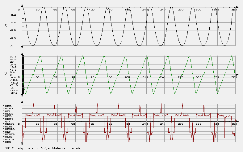
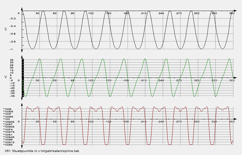
Typical for the use of vertex tables in mechanism calculations is that the original vertices have measurement or rounding errors, so that the derivatives, especially the acceleration cams, look "noisy". Then it is important to smooth the bases within definable tolerances in order to use them for further calculations at all.
Our software OPTIMUS MOTUS offers suitable smoothing algorithms.
Example:
Path-time table with speed (green) and acceleration (red) from an NC file (rounding to 3 decimal places):
... and after smoothing with OPTIMUS MOTUS:
We assist you with our motion design to let your machines run faster!
To the homepage of Nolte NC-Kurventechnik GmbH
Start Mechanisms Kinematics CamDesign Indexing Servo+PLC Training Service CamCalculation Software Imprint PrivacyPolicy
Examples General MotionLaws RangeExtension CollisionsOptimization EnergyOptimization HS-Profiles Splines
11/06/21
• Software OPTIMUS MOTUS ® /
DasNolte ®
• All types of Cam Calculations
• Performance Optimizations
• Trainings and consulting
• App and Software Development
• PLC Motion Software
Cams, Mechanisms, Motion Design. Faster Machines. Since 1965.
