Collision optimization
Collision optimization is a very effective method for systematically bringing complex motion controls with cam gears and servo axes to high performance. With collision optimization, you consistently get more throughput from the mechanics (often more than 40%) without making the machine more expensive.
Since 1973, Nolte NC-Kurventechnik has been specializing in the design and simulation of motion sequences in complex systems with cams, linkages and servo drives and offers collision optimization as a fixed price service (in addition to software). The scope of supply includes DXF files of the cam tracks and the mechanism starting position, NC programs for producing the cams as well as diagrams, charts, tables and animations
The term "collision optimization" is composed of "motion optimization" and "collision control".
The principle is simple:
You optimize the overall motion diagram and at the same time graphically simulate the motion sequence.
You try to avoid the collisions in the motion simulation scarcely and distribute thereby the dynamic loads evenly on all single drives and over the time, thus to minimize them. Ultimately, all individual drives should theoretically achieve the same, highest possible cycle rate. You always work on the most critical part of the movement design step by step and defuse it until you can no longer find an approach for improvement.
In practice, this iterative procedure is quite intuitive to implement, although there are a number of evaluation criteria to consider. However, the simulations and diagrams for accelerations, forces, moments, pressures, etc. show the way. You just have to look at them.
The more experience you have with the method, the fewer iterations you need.
However, the right tool for collision optimization is important. It needs to update simulations and ratings quickly, within seconds. Our OPTIMUS MOTUS software is ideal for this. It has been developed exactly for such optimizations.
Skip to ...
- Continue in the text
- The right tool
- Example collecting wheel
- Example bending machine
- Example book stacker
- Example state driven parts for chewing gum single pack
- Example folding tools
- Example bottle labeler
- Detailed pick & place example with log of performance improvement
- Calculation
To the homepage of Nolte NC-Kurventechnik GmbH
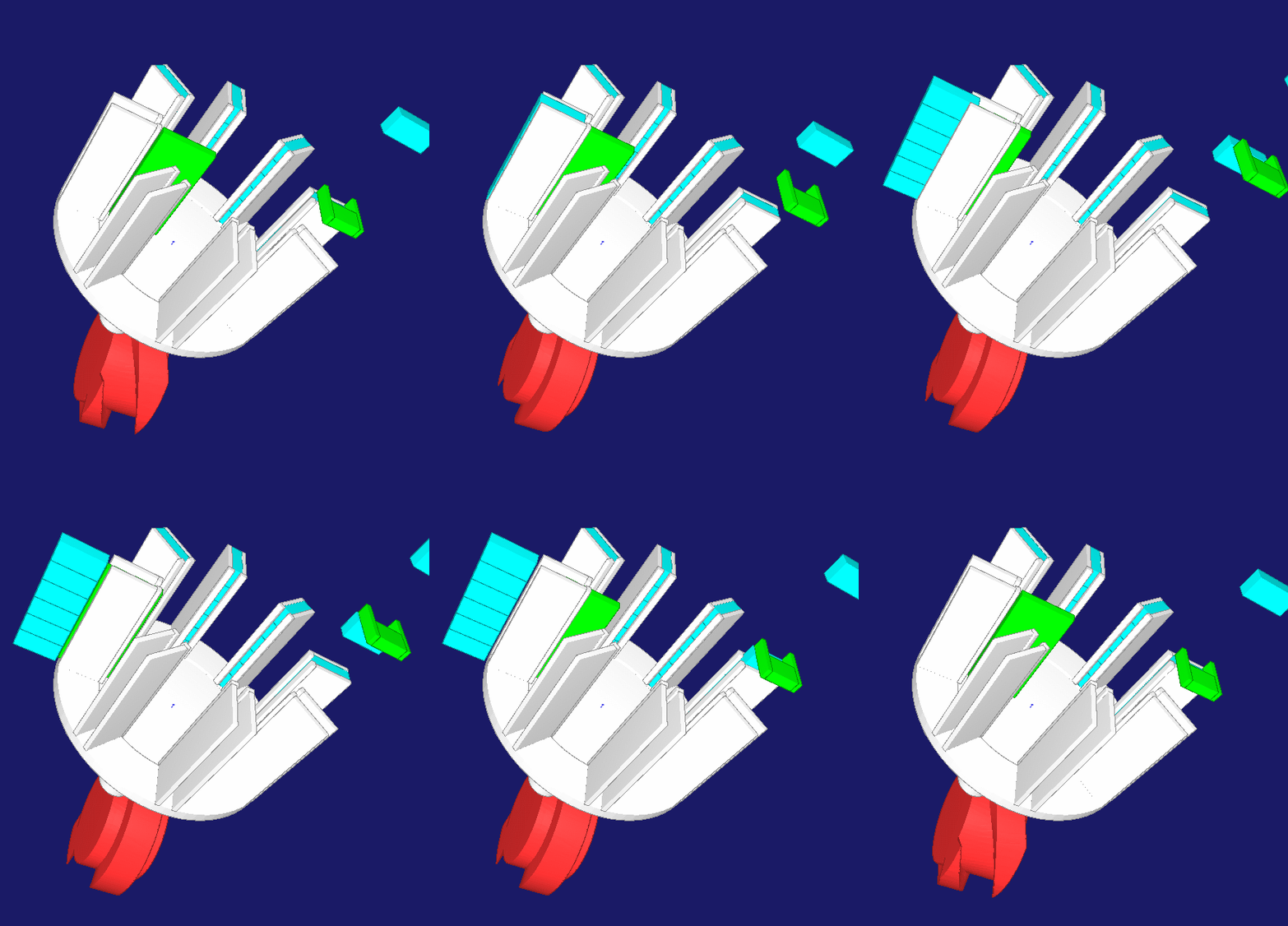
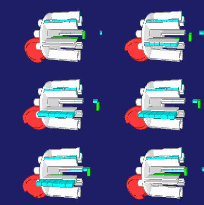
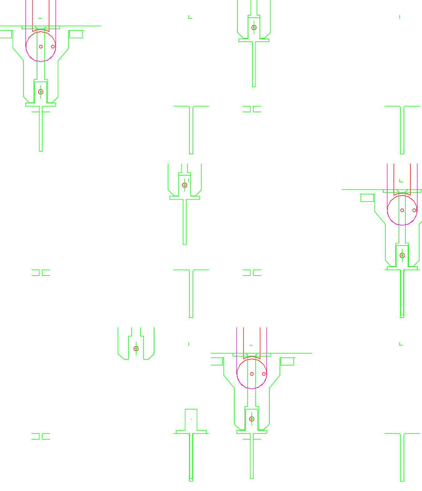
A rake collects 3 to 8 individual items in a collecting wheel until a block of items is complete. Then the collecting wheel rotates by one pitch. After 180 degrees of rotation, the article block is ejected into the case packing machine. For the stepwise rotation of the collecting wheel only the very short time between two individual items remains, in practice about 25 ms. In order to achieve this switching time with a variable number of individual items with a compact mechanism, a servo drive is combined with a cylindrical indexing cam drive. In response to a trigger signal, the servo accelerates the mechanical cam to maximum speed without the collecting wheel rotating. During a switching phase at a constant cam speed, the collecting wheel continues to rotate by one pitch. Then the servo brakes without rotation of the collecting wheel until it comes to a standstill after 360 degrees of rotation. The inertia of servo motor + barrel cam and collecting wheel + article do not simultaneously cause a drive torque, so that the maximum torque decreases. The servo has enough time in the dwell phase of the collecting wheel to bring the cam to speed. The cylindrical cam can be kept small because it stands still for a large proportion of the overall cycle of a multipack.
The entire movements were matched with OPTIMUS MOTUS in such a way that the maximum and effective torque on the servo are minimal and thus the cycle rate maximal. The required cam rotation angle for the indexing motion, the cam width and the cam diameter were also optimized, the barrel cam was recalculated and the resulting moment of inertia of the cam was taken into account.
Example Bihler bending machine
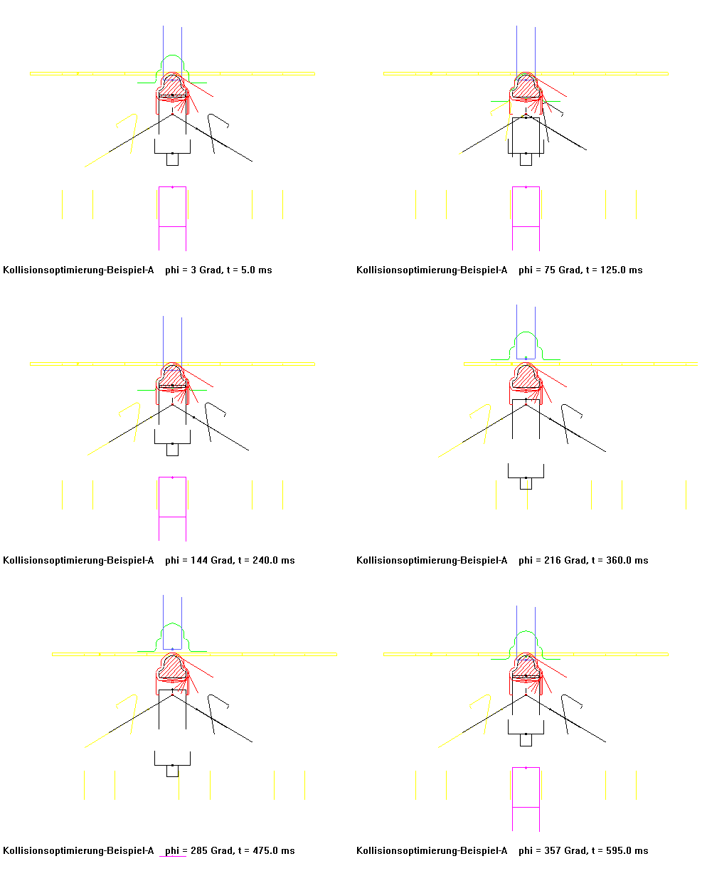
A bending machine initially produced pipe clamps at 70 cycles per minute using conventionally calculated and NC milled cams. After replacing the cams in this machine with a collision-optimized set of cams, it finally produced 250 (!) articles per minute, while smoothness was improved.
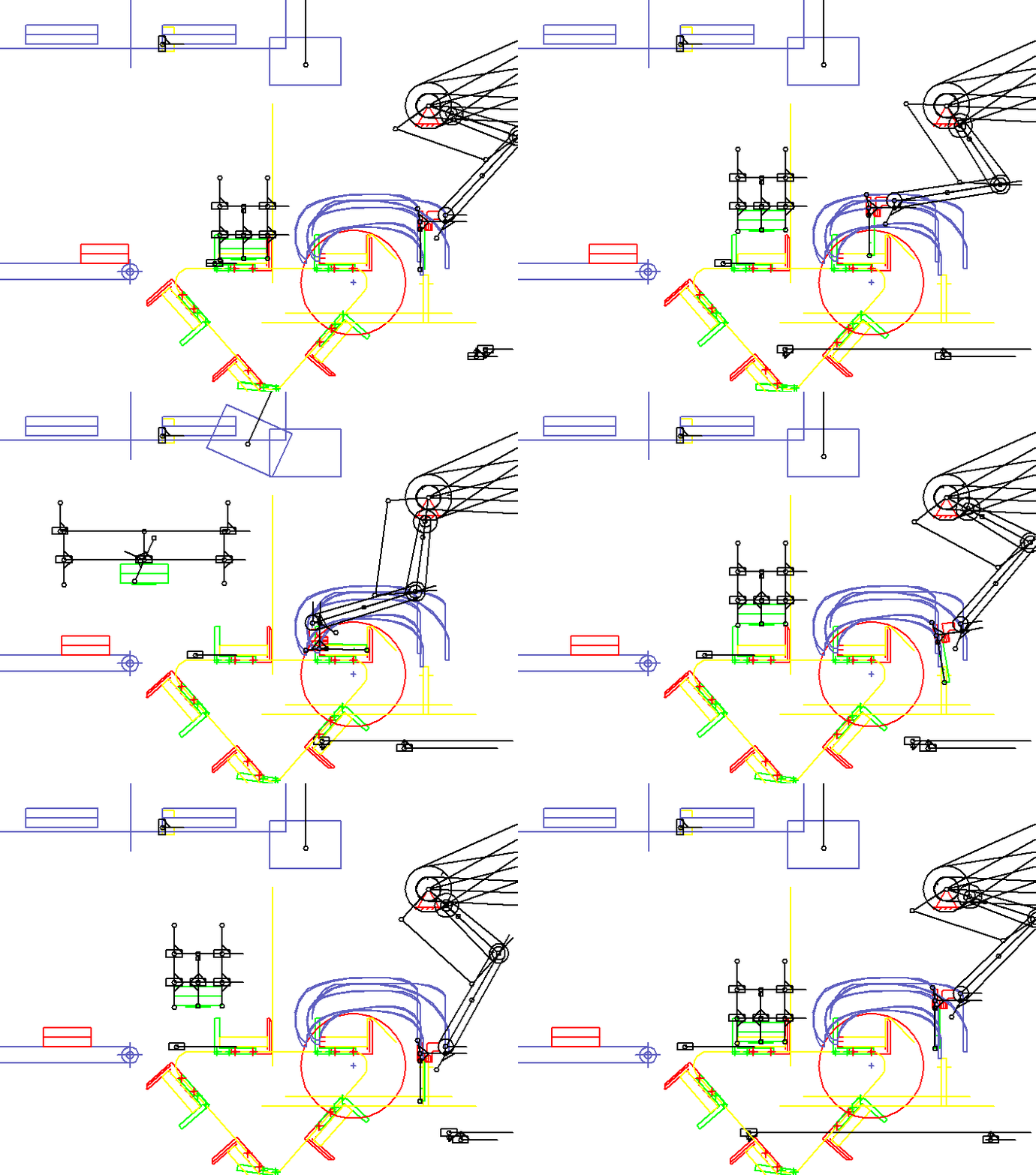
A pair of gripping arms synchronizes itself to a stream of books, grabs two books, pulls them up and places them in transport areas on each chain. If the XZ plane is visible in the animation, the book flow moves in Y direction. The animation shows only one of the gripper arms. The second is offset in depth (in Y direction).
In the animation, the book transport and the co-movement of the grippers on the bottom right are only sketch-like with rectangles and lines with variable length. It is important to see that book and gripper drive synchronously or which path difference results if the synchrony is not maintained exactly.
In the transport compartment several books are collected, and a gripper must approach each storage position differently. Overall, the quite flexible books must be stacked without kinks, grooves or similar injuries.
When a certain number of books have been collected in the transport compartment, the transport compartment is moved by one pitch.
As an option of the system, the stacks are raised in the moved transport compartment by a turning station, rotated and stored again on the incoming partial stack, while the transport compartments move one step. In the transport compartment in front of the delivery conveyor (left), several partial stacks accumulate. The turning station is shown in two views in the top left corner: turning on the top, underneath laying down. After a fixed number of sub-stacks, the turning station places the entire stack on a slow and steadily running discharge belt.
The system contains 10 servo drives with electronic cams, and the format variety is huge. For such a system, we have created a parametric model that generates its own motion diagrams for all format variants, including collision checking, so that the system can process any format with the maximum possible cycle rate.
For such applications, we develop source codes or function blocks for PLC programmers.
Example chewing gum packing (event driven parts)
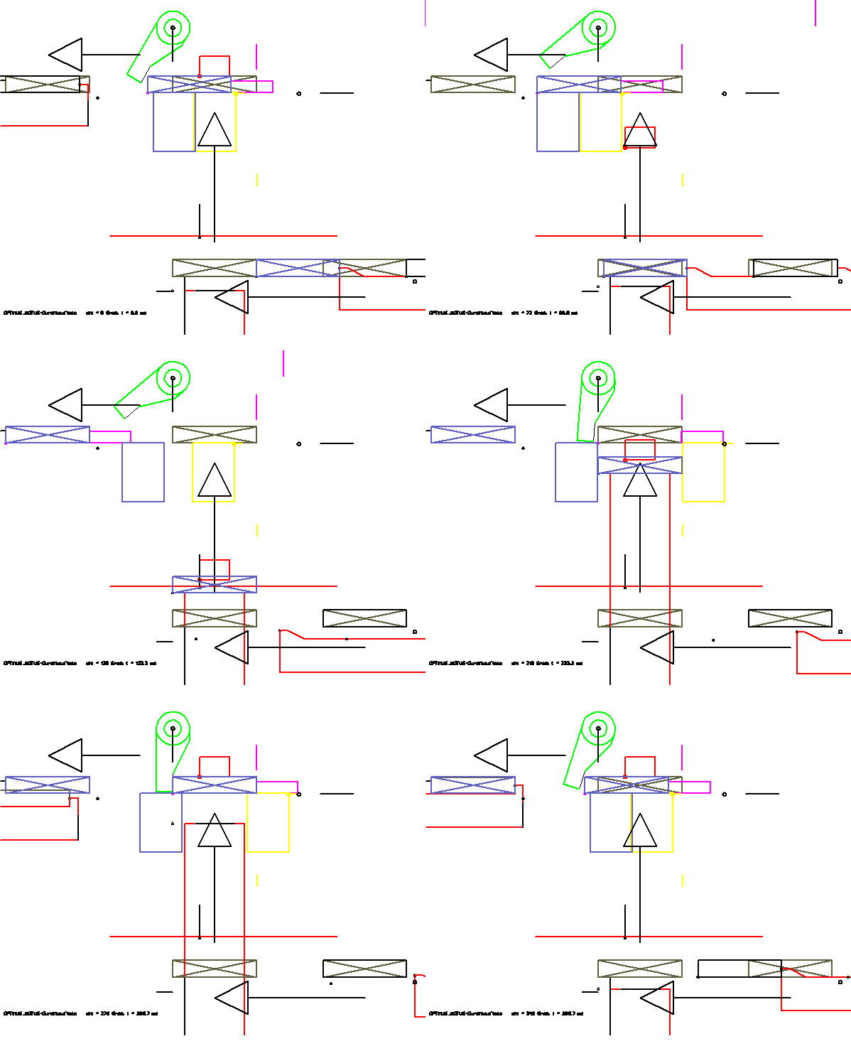
In this animation, the moving parts are sketched only by a few lines. Such a simulation can be created on an ad hoc basis, without modeling in the CAD system. A special feature of this animation is the way the movement of the chewing gum (rectangle with cross) is displayed. It is passed from tool to tool. Thus, the passage of the article by the station is particularly vivid. In the OPTIMUS MOTUS software, a special feature is available, the "event driven parts".
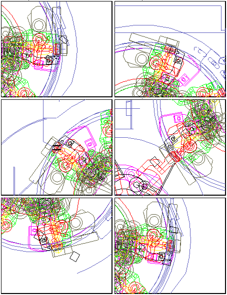
Folding processes are presented here in order to pack caramels in continuous operation in paper or foil. The camera position is special here. It moves in sync with the article. The interdependencies between the individual movements are particularly complicated in this application. But the cycle rate with >1000/min is pretty high.
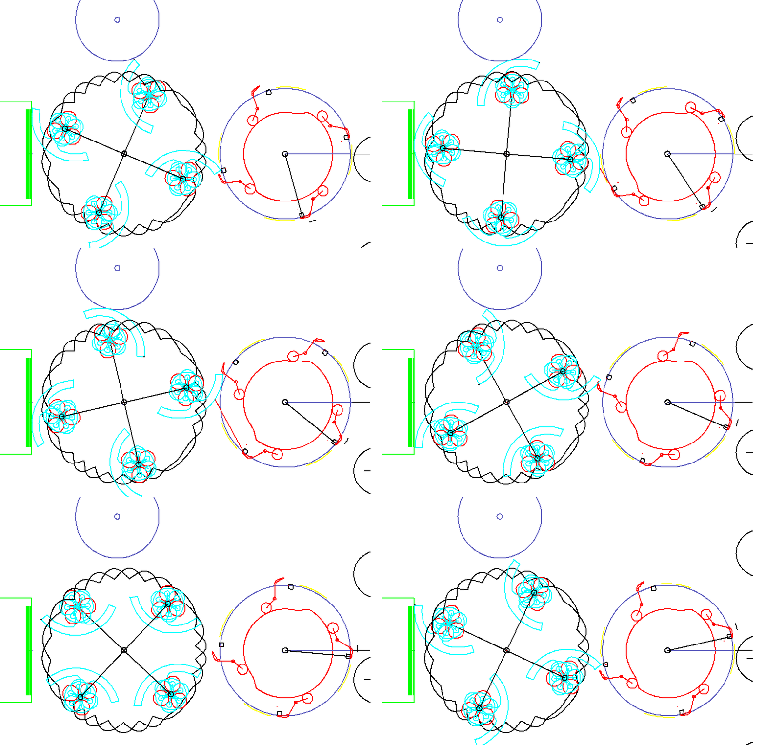
The animation shows a cold glue labeling. Labels are glued with segments, pulled out of a magazine and finally removed with grippers to be applied on bottles.
More about collision optimization
The graphical simulations can be 3D simulations such as the collecting wheel or 2D animations such as book stacker, chewing gum single pack, folding or gluing.
3D is cooler, but 2D is more practical for collision checking because you can see overlaps of parts right away. In 2D you do not have to find the right perspective to distinguish between gap and collision. 2D animations can be graphically organized so that multiple collision points are displayed close together and you do not have to jump between views for monitoring. These representations are 2D drawings with multiple views.
Of course, the simulations can include the complete detailed geometry of all moving and stationary parts, including screws, springs, energy chains, cables, etc., but that is by no means required. If the animations are not supposed to impress somebody at the same time, it's enough to show only the geometry that may take part in a collision. These are sometimes just a few lines or arcs.
Collision optimization is considerably more effective than just picking "the right" motion law.
By simply exchanging laws of motion, the achievable cycle rate can be influenced only slightly (usually about 5% in practice).
With collision optimization we have increased the speed very often by 40% or more, in some applications even by 250%!
Finally, the cycle rate of the entire system is always limited by a dynamic limit at one critical axis.
Collision optimization taks into account all dynamic limits (
- Available space,
- Velocity,
- Acceleration,
- Jerk function,
- Force,
- Maximum torque,
- Effective torque,
- Pressure,
- Tensile strenght,
- Minimum service life,
- Vibration excitation
etc.) to design motions for all cams and servo drives in a way that the overall system can achieve the highest possible cycle rate. The dynamic load is distributed evenly across all movement axes and also over time. All axes of motion (cams, servo drives, etc.) should be used equally intensively. More heavily loaded drives and movement phases are relieved, while more dynamic drives and phases of motion are pushed.
This balancing of loads is a kind of "social thought" for the coexistence of the movement axes.
In operation with a predetermined nominal speed you get much dynamic reserve and low wear.
For each dynamic criterion and each axis of motion it is possible to estimate the theoretically achievable cycle rate.
Example:
A servo axis moves a mass back and forth with a certain motion profile. Other loads than inertia are not relevant. The motor can apply 9 Nm. At 100 cycles/min, a maximum required drive torque of 4 Nm is calculated.
Since the drive torque resulting from inertia increases quadratically with the cycle rate, the cycle rate can be increased by a factor of 1.5, because 1,52 = 9 Nm / 4 Nm. Theoretically, the axis could thus be operated up to 150 cycles/min before the drive torque becomes too large.
Similar estimates can be made for all dynamic criteria and all axes. The aim of the collision optimization is to make the smallest estimated cycle rate as large as possible. In practice, these estimates are not necessarily explicit. Instead, one simply checks which dynamic load is particularly large in relation to the corresponding limit and defuses this point.
You can also approach the overall optimization in this way:
To evaluate the motion design, you first set a specific cycle rate and optimize all motion design movements to keep this speed.
If this is not possible, slightly reduce the cycle rate and try again.
If it is possible, increase the cycle rate and also optimize again!
Finally, with this iteration, you will also find out which cycle rate the system can mathematically achieve.
This sounds complicated, but in practice it is a very intuitive process. Experience will help, of course.
"Optimizing" also means giving the critical sections of motion on the axes more time. This time must be taken away from other axes and movement sections, otherwise movements would overlap in time so that the moving parts collide. In the motion simulations you can see the collisions right away.
The right tool for collision optimization
Collision optimization is a systematic and consistent motion design for the machine, taking into account a variety of dynamic evaluation criteria.
Collision optimization is only fun if the individual iteration steps can be carried out quickly, otherwise the procedure would no longer be intuitively applicable. As a user, you must quickly recognize and learn about the impact of certain changes in movement design.
You definitely need software for collision optimization, and the software has to offer:
- Interactive movement design with many features to create motionss (for the dynamic quality of movements)
- Graphical simulations (for collision checking)
- Short calculation times for the simulations (a few seconds)
- Quick provision of current values for all evaluation criteria
The software OPTIMUS MOTUS was designed to meet these requirements.
We and many other users have been using them for decades with great success for the dynamic optimization of complex motion control systems.
Collision optimization is movement planning and acts like a map or a navigation system when driving a car.
If you begin to design movements on the factory floor and at the machine control, eg with the functions commonly used today for moving support points in the cam editor, and testing on the running machine, you have virtually no overview over the load factors for the individual evaluation criteria. In addition, it is risky to pre-scan with the running machine in collision-related areas, so you would better keep your fingers off and instead lose performance.
Graphical simulations are often created in practice in the CAD system, if there is a kinematic module installed there, or in a MBS program (multi-body simulation). This works, but has disadvantages in the context of collision optimization:
- Modeling the required geometry is relatively expensive.
- Calculations and simulations are slow.
- It usually lacks a powerful motion design tool.
Time-dependent movements can often only be introduced in these systems via camd track splines. Then a dummy cam has to be calculated provisionally and integrated into the model in order to to simulate the motion sequence at all. This remedy is cumbersome if you want to change the cam frequently in the context of collision optimization.
In OPTIMUS MOTUS you can specify movements at any point directly with motion design, without detouring over workarounds.
Software for MBS (multi-body simulation) is very powerful in terms of model depth and detail. However, the computation times are also significantly greater, and model complexity is more difficult to handle.
Collision optimization with OPTIMUS MOTUS offers the best ratio between optimization effort and increased machine performance.
Example pick-and-place application
2D pick & place application (PnP)
By means of a simple example with only 2 motion axes we want to see which performance increases result with different optimization techniques. In "real" tasks, often much more movements have to be optimized against each other (typically 4-10, sometimes more than 40).
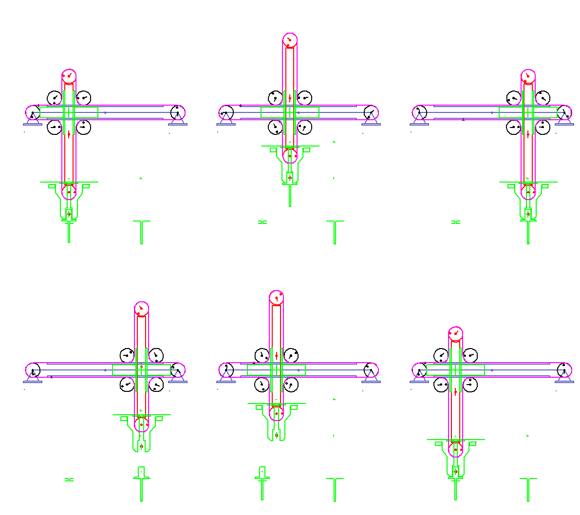
A servo-controlled mounting unit pulls pins out of a magazine and inserts them into an assembly.
The pins stick 30 mm deep in the magazine and should also be inserted 30 mm deep into the assembly.
The gripping and assembly points are horizontally (X) 100 mm apart, vertically (Y) at the same height.
The vertical path of the gripper should not exceed 50 mm.
The gripper reaches a length of 10 mm and opens 2 mm (1 mm on each side).
We need 40 degrees time angle for the opening movement.
The movement characteristic of the opening and closing movement is not known exactly.
All movements should be smooth, ie without jumps in path, speed and acceleration.
We aim for 100 cycles/min.
For the sake of simplicity, both axes of motion are only evaluated with the maximum acceleration.
The accelerations in horizontal and vertical direction should have the same weight.
The goal is therefore the smallest possible maximum acceleration in the X and Y direction.
You will see how we can reduce the acceleration in this example from 125.7 m/s2 to 17 m/s2.
Motion design 1:
A first movement design could look like this:
- Consistent sequential programming of individual movements (as usual with NC axes)
- with the popular movement law "Inclined sine"
- and free distribution of transitional periods
- with utilization of the full vertical stroke
"Sequence programming" means that a movement phase (open, close, up, down, left, right) may only start when the logically preceding movement has ended. With NC controllers, this allows safe processes, since each step is not started until the previous step has been completed successfully.
The following maximum accelerations result:
In horizontal direction X:
amax_x = 90.5 m/s2
In vertical direction Y:
amax_y = 125.7 m/s2
These maximum accelerations can be found in the following diagrams always in red color on the left side.
Motion design 2:
It makes sense to consider the symmetry properties of the displacement plan:
- Horizontal driving back and forth should each take the same time
- all vertical strokes should take the same time
Result:
amax_x = 35.3 m/s2
amax_y = 125.7 m/s2
Motion design 3:
In the next step we want to consider whether the inclined sine is the best law of motion. It has a large acceleration characteristic (Ca = 6.283). The smallest possible Ca value for dwell-to-dwell applications is the squared parabola (Ca = 4), but it is jerky. Although the polynomial of the 8th degree with Ca = 4.667 has a smaller acceleration characteristic, let us choose the modified acceleration trapezoid ("Modified Trapezoidal") with Ca = 4.888, because the maximum value of the jerk function is smaller.
Result with motion law "Modified Trapezoidal":
amax_x = 27.5 m/s2
amax_y = 97.8 m/s2
Motion design 4:
It should also be taken into account that the vertical stroke (50 mm) is half the horizontal stroke (100 mm) and therefore causes half the acceleration at the same transition angles ("tima angle differences"). To get the same acceleration in X and Y, the transition angles of X and Y should be set in the right proportion to each other.
The horizontal paths should be covered in approximately 58 degrees time angle and the vertical paths in approximately 41 degrees time angleto get balanced acceleration values.
Result:
amax_x = 52.3 m/s2
amax_y = 52.3 m/s2
Motion design 5:
From the motion design we know the technique "range extension".
If we allow a small error of 0.5 mm for the gripper position in X and Y at all theoretical transition points and allow the individual movements to start earlier and end later, the accelerations continue to decrease:
amax_x = 38.1 m/s2
amax_y = 41.6 m/s2
Motion design 6:
Finally, we must conclude that we have not yet taken advantage of much potential for optimization after selecting a motion law, balancing the time distribution and applying range extension:
- When pulling out the pin from the magazine and during assembly, the pin and thus the gripper needs to move exactly vertical over 30 mm only, not over almost 50 mm total distance.
- After the beginning of each opening, the gripper only has to move approximately vertical. There may be deviations in the horizontal direction if the gripper and pin do not touch each other.
- The vertical movements may overlap with the opening and closing movements of the gripper. The gripper should effectively stand still in picking and dispensing position when the gripper is less than half open.
With these points and balanced redistribution of times we get the following result:
amax_x = 17.0 m/s2
amax_y = 16.5 m/s2
The motion diagram shows that we caught an asymmetry again. This is due to the different lengths of 30 mm and 14 mm, which the gripper has to move exactly or approximately vertical.
During the empty journey back one can do without the small rest in the position Y = max and instead use a reversal point.
The vertical stroke 50 mm does not have to be fully utilized during empty travel. Optimum acceleration results in a slightly smaller vertical stroke.
Up to here, the optimization has been quite convenient, mainly by shifting vertices 5, 2 or 1 degree on the timeline. The last subtleties of optimization, which set amax_x and amax_y even more exactly the same and would presumably also press a few tenths of an m / s2, then play off in even smaller increments of optimization and bring with the same effort ever smaller performance increases.
Therefore, the optimization should be finished at this point. The result is impressive.
Conclusion:
We started with a first interpretation "from the gut" and had a maximum acceleration of 125.7 m/s2 .
Using classical motion design methods, we have been able to reduce the acceleration to 41.6 m/s2 (design 5), which is remarkable.
The collision optimization has reduced the acceleration even further to 17 m/s2 , and that's pretty awesome.
To conclude the collision-optimized motion sequence as an animation:
To the homepage of Nolte NC-Kurventechnik GmbH
Start Mechanisms Kinematics CamDesign Indexing Servo+PLC MotionDesign Training Software Service CamCalculation Imprint PrivacyPolicy
General Specials TheRightTool Folding CollectingWheel BendingMachine BookStacker StateDrivenParts BottleLabeler PnP_Performance
11/06/21
• Software OPTIMUS MOTUS ® /
DasNolte ®
• All types of Cam Calculations
• Performance Optimizations
• Trainings and consulting
• App and Software Development
• PLC Motion Software
Cams, Mechanisms, Motion Design. Faster Machines. Since 1965.
