Linkages
Linkages are mechanical structures with revolute, linear and cam joints for transmitting movements or for guiding points or planes.
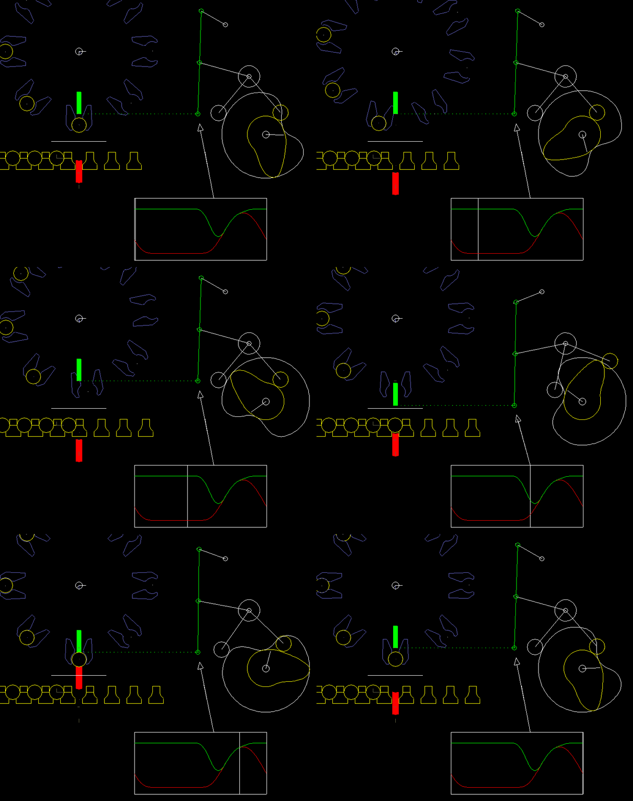
Linkages (couplings) are often combined with cam gears, servo drives or gearboxes. They transfer the movement from a cam to the possibly distant working tool and thus to the point of action. At the same time, they also translate the cam stroke.
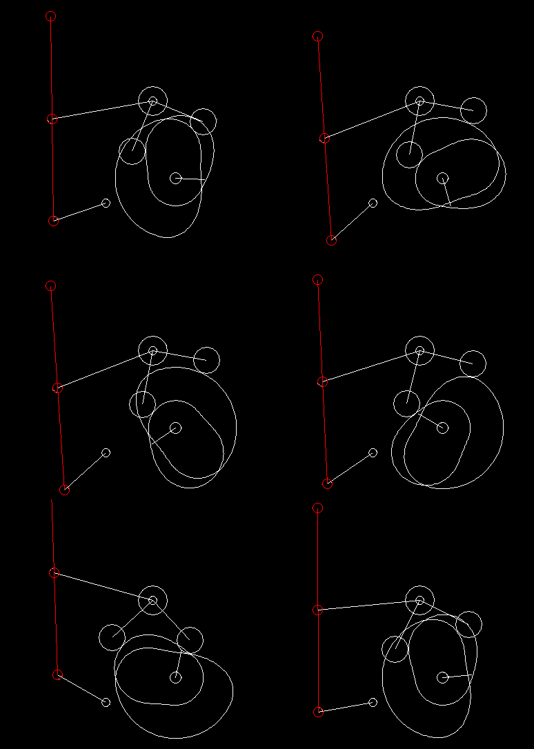
In case of complex motion controls with linkages, we generally specify the movement at the point of action and use our software OPTIMUS MOTUS to calculate the resulting movement of the cam follower or the servo drive by inverse kinematics.
Linkages transmit movements nonlinearly. The speed at the output is therefore not proportional to the drive speed. For synchronous movements and to avoid collisions in complex motion sequences, it is important to take this into account.
Because of the non-linearities, coupling gears also have very interesting properties on their own and enable simple, robust and harmonious running solutions for practical movement tasks.
Example:
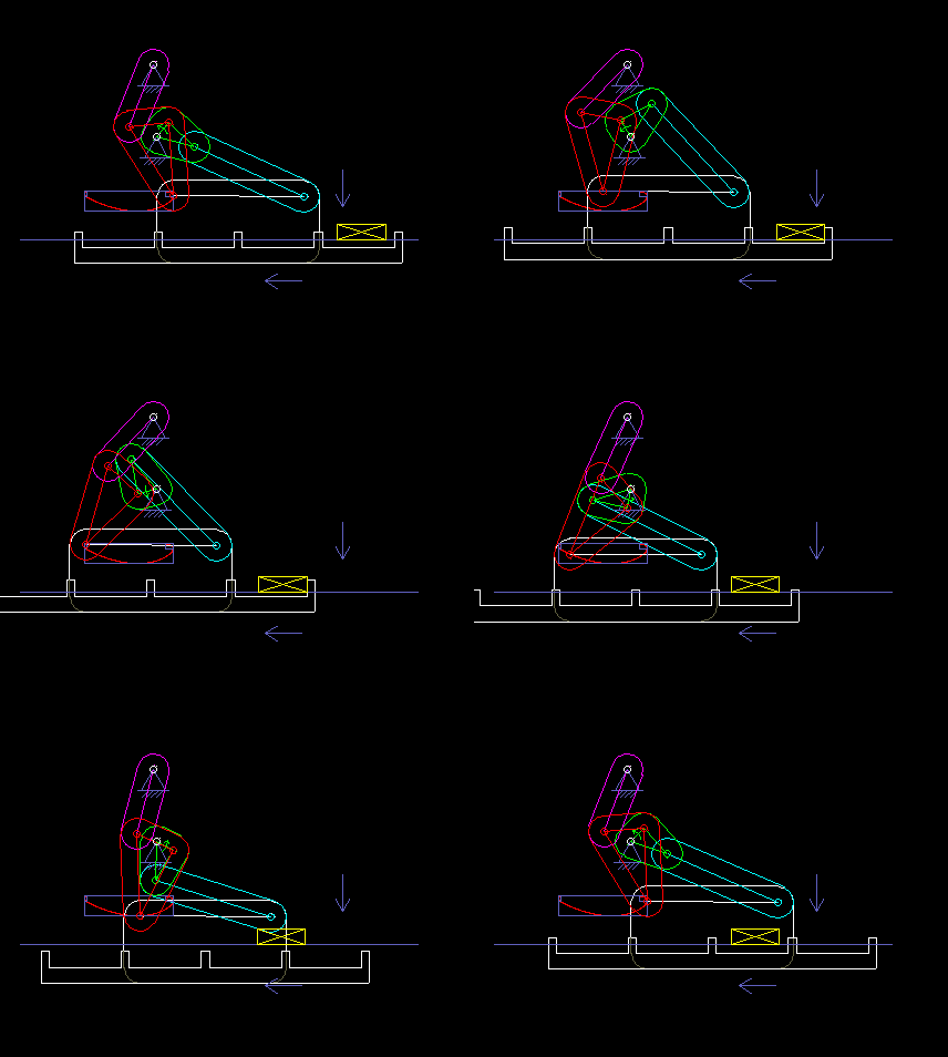
The following animation shows a six-bar linkage (frame + 5 moving parts), which is used in a packaging machine as a transport rake. It is based on a four-bar linkage, which creates a "bread-shaped" coupling curve suitable for the transport, and an attached dyad, with which the rake is held horizontally everytime.
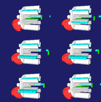
Once, when I visited the production of a confectionery manufacturer, I noticed a 50-year-old machine that contained no cams and certainly no servo drives, and that packed chocolate. Such solutions may not be up-to-date anymore, but they also show that linkages alone enable complex motion control!
In machines, four-bar linkages are often used.
Servo drives are often combined with slider-cranks to create an oscillating stroke from the input rotation of the servo drive or gearbox output.
In mechanical presses, sometimes multi-bar linkages are used to achieve a press ram motion that is favorable for the forming process.
But you also know some examples of linkages from everyday life:
- Mechanics of umbrellas
- Harbor cranes
- Excavator
- Hinges in kitchen cabinets
- Windshield wipers
- Toy pantograph
- Mechanics on the wheels of a steam locomotive
- Mechanics on cabriolet covers
- Loppers
- Lifters
Our topics in software, consulting and design:
- Linkage analysis
- Combination of cams, servo drives and coupling gears
- Calculation modules for kinematics and kinetostatics in C and ST
- Software source codes for kinematic transformations
- Digital twins for mechanism structures
- Linkage synthesis
- Special considerations on four-bar mechanisms, slider-cranks, crank loops, six-bar mechanisms, multi-bar linkages
Skip to ...
- Four-bar mechanism
- Slider-crank
- Calculation (analysis) of coupling gears
- Linkages combined with cams
- Linkage synthesis
- Singular mechanism positions
- Dyad library
- Software
- Calculation
To the homepage of Nolte NC-Kurventechnik GmbH
Four-bar linkages
Probably the most well-known and most studied coupling mechanism is the flat four-bar linkage, a coupling gear with four bars (parts) exclusively with revolute joints. The frame counts as a bar.
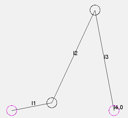
Four-bar linkages are used to transmit motions and to guide points and planes.
Their simplicity is based on the principle: the less moving parts, the better.
Four-bar linkages often serve as the basis for more complex mechanism structures.
At the time of the graphical transmission analysis, four-bar linkages were often used as replacement to study, for example, characteristics of cam gears.
Let lmin be the smallest, lmax the largest, and l' and l" the other two bar lengths.
According to the theorem of Grashof, the shortest transmission element lmin is able to rotate with respect to its neighbors, if:
lmin + lmax < l'+ l"
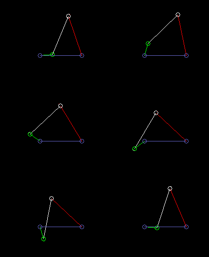
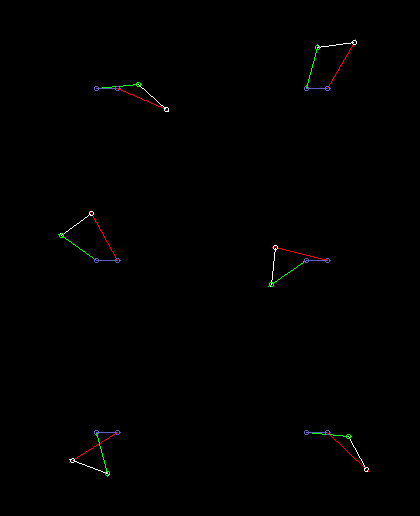
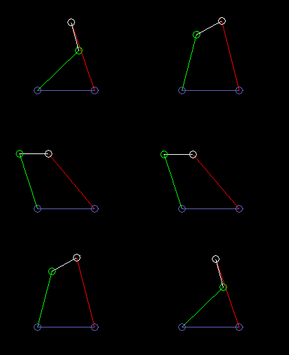
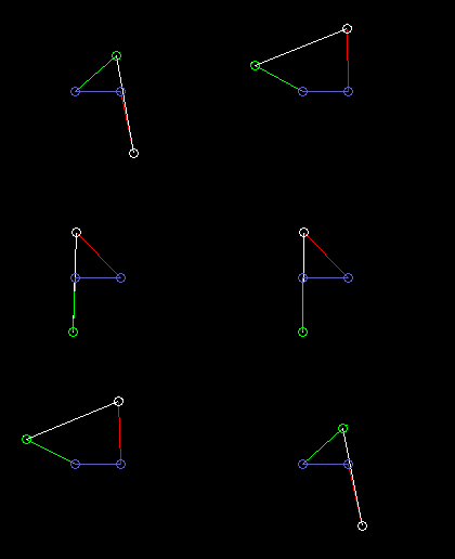
The following animations show examples of different variants of four-link mechanisms.
Drive = green
Coupler = white
Output = red
Frame = blue
Rocker-crank:
lmin here is the crank length (green), ie the length of the driven bar (part).
Double crank (drag link):
lmin here is the length of the frame, so the distance from crank pivot to output bar fulcrum.
Double rocker:
lmin is here the coupling length.
Inside oscillating double rocker (total rocker):
lmax here is the length of the frame. And it is lmin + lmax > l'+ l".
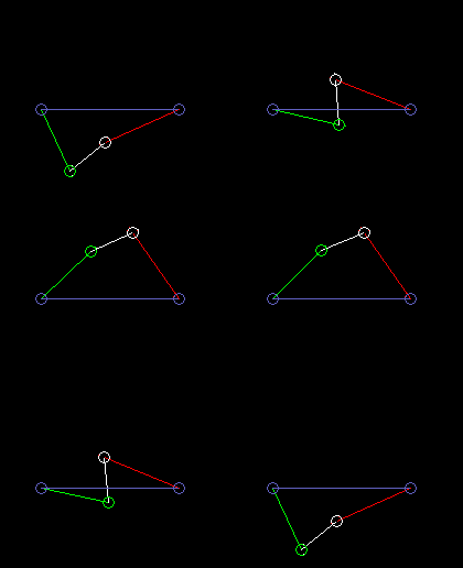
Outside oscillating double rocker:
lmax is the coupling length.
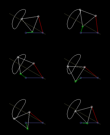
If the kinematic dimensions are selected appropriately, ie the link lengths and the position of the coupling point on the coupler, the coupling point is approximately guided on a predetermined curve. Because of the simple transmission structure with correspondingly few parameters, however, not all curves can be approached equally well.
This animation shows a four-bar linkage with a symmetrical coupler curve for the approximate straight-line guidance of the coupler point:
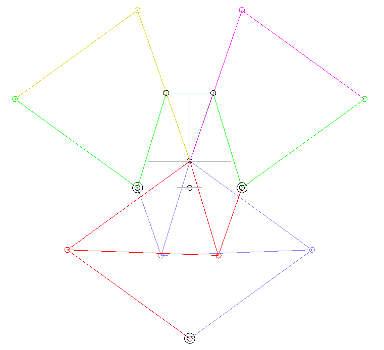
According to the theorem of Roberts and Tschebyschev, for a four-bar linkage that produces a certain coupler curve, there are still two completely different ones that produce exactly the same coupler curve.
Roberts's theorem then helps to find a four-bar linkage for the given space or for the right drive link.
Slider-crank
The slider-crank is also a very common four-bar linkage. A rotating drive (the "crank") moves an output carriage by means of a coupling bar ("coupler"). In addition to the fixed frame, the crank and the coupler and the output slideer count as a bars or links.
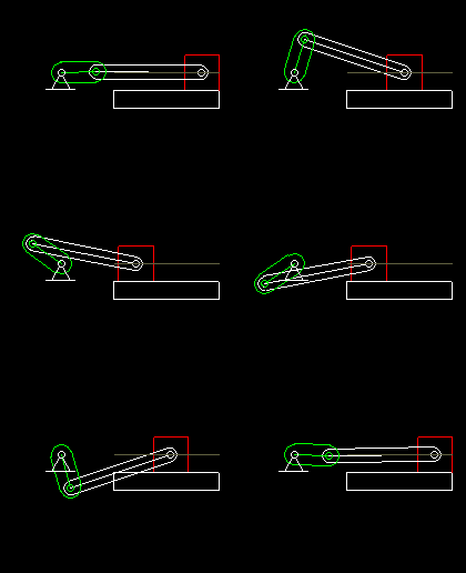
The slider crank is mainly used as a transmission gear to turn a rotating drive motion into an oscillating linear output movement.
Slider-cranks are combined with both servo drives and cam gears. This animation shows a cam gear with rocker arm, in which a slider crank transmits the movement to the output carriage.
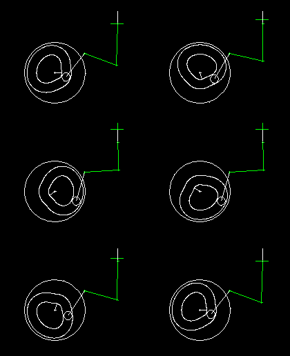
When designing the servo drives with rated torque and peak torque, it is very important to consider the non-linearity of the slider crank drive, otherwise completely wrong loads are expected.
In combination with servo drives, the centric slider-crank is most often used, where the straight line, on which the coupler end point moves, passes through the crank pivot point:
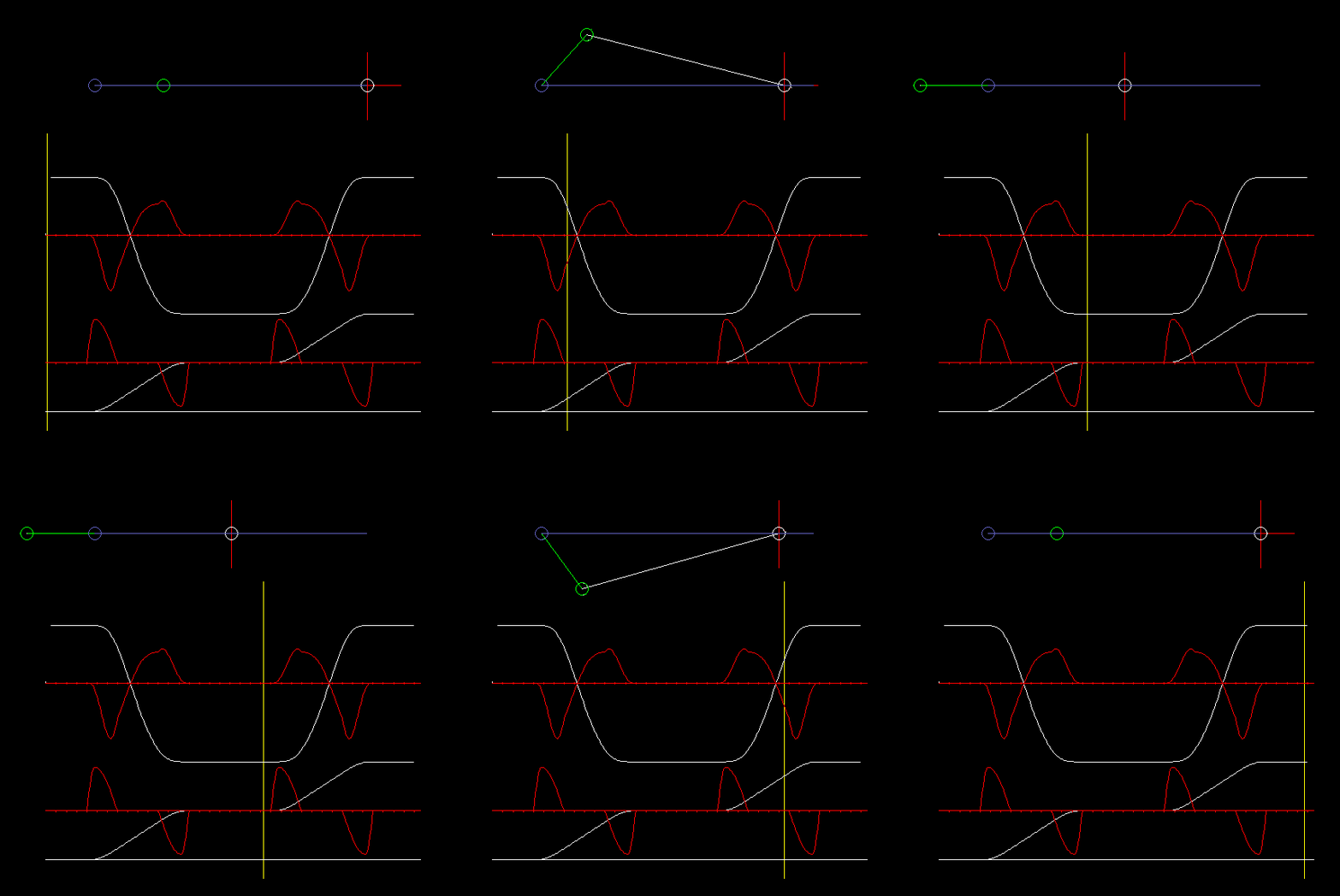
The animation shows a centric slider-crank and diagrams for travel and acceleration on the slide (top) and the servo drive (bottom).
In case of the revolving centric slider-crank, the crank covers 180 degrees of drive angle for both strokes (to the left and to the right).
On which side of the straight-line the slider-crank runs is irrelevant for the transmission behavior. With the same motion characteristic on the crank, the same motion can be generated on the output, whether the crank rotates clockwise or counterclockwise or oscillates above or below the output slider line.
The slider crank has properties that make it particularly attractive for motion transmission:
The slider keeps its end position very accurately even if the servo just approaches its end position inaccurately. The closer the mechanism approaches an end position, the less the carriage moves in relation to the drive angle.
In the end positions, you can use the "toggle effect" to generate high forces on the output with a small drive torque. This is often used for pressing, embossing or forming. Far away from the end positions, relatively large strokes can be generated. The toggle effect can be strengthened by concatenating two toggles ("double toggle").
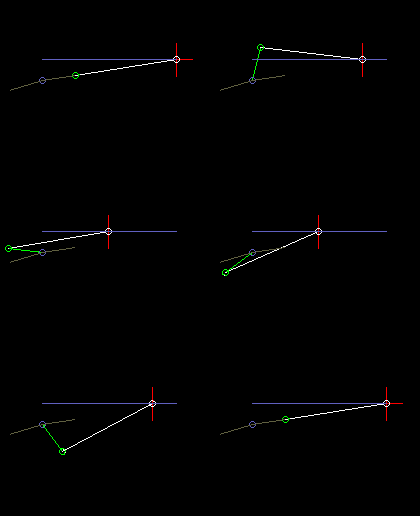
In the eccentric slider-crank, the crank passes through different angles for both stroke directions, ie the eccentric crank does not work symmetrically. Here it is quite important on which side the slider-crank works, based on the connecting line from the crank pivot to the coupler end point.
The animation above with cam and output slide is an example of a slider-crank with large eccentricity.
Calculation (analysis) of linkages
By kinematic "analysis" of linkages is meant to determine the position of all moving parts after motion constraints have been made. In this case, in each linkage position as many independent motion specifications are necessary as the mechanism has degrees of freedom.
There are several alternative approaches to linkage analysis, for example:
1. The "drawing-based calculation method"
This method is very old and has been used when mechanisms were not constructed with computers, but on the drawing board.
In the case of the drawing-based calculation method, a linkage position is first of all constructed using a compass, ruler and pencil. These drawings eventually consist of several connected triangles. The individual construction steps are then algebraically modeled to calculate successively lengths and angles on the triangles using the cosine theorem, sine theorem, Pythagorean theorem and generally sine, cosine and tangent functions. Finally, one comes to a long series of calculation formulas to calculate the output quantities of the kinematic analysis from the motion specifications.
It is clear that the entire complicated formula derivation must be completely redone for each mechanism and also for each type of motion specification.
If you want to specify the movement alternately on the drive and the output, then two formula series must be derived!
The formulas are long and cumbersome because of the trigonometric functions, and at the latest when speeds and accelerations are to be calculated, the process is no longer fun.
As a child, I saw in the 1970s how my dad made such drawings on the drawing board, then developed formulas and finally programmed them with his Diehl Alphatronic computer.
The drawing-based calculation method has another major disadvantage: not all mechanisms can be calculated with it.
For some combinations of gear structure and motion specification, no analytical formulas can be derived!
2. The dyad (module) method
The dyad method is an algorithmic improvement of the drawing-based calculation method.
With the drawing-based calculation method, you often derive basically the same formulas, and many things are repeated. Therefore, it makes sense to develop reusable subroutines for logical sub-steps of the kinematic analysis.
Each subroutine corresponds to an defined arrangement of linkage elements together with defined input and output variables.
Such a combination of linkage elements, input variables and output variables is called "module" or "dyad".
We ourselves have calculated linkages up to about 1995 preferably according to the module method, because this analytical method allows particularly fast and very exact calculations.
These modules are still available and usable in the software, but have now been replaced by a better approach.
Because the module method also has serious disadvantages:
- If you want to specify movements at different points of the mechanism, eg at the drive and at the output, new module sequences must be defined each time.
- Some mechanisms can not be calculated with the module method because the analytical derivation of the calculation formulas is not possible. Such mechanisms can only be calculated using iterative methods.
- Compiling modules for the mechanism computation is quite abstract and strongly reminiscent of the programming of software. In our software trainings 20 years ago, we have often experienced how difficult it is for engineers to work with the abstract modular concept.
An example shows how confusing the analysis of linkage can be with the module method.
Incidentally, the module method can also be used for the kinetostatic calculation of joint loads in mechanisms. But that is very abstract and cumbersome and quite uncomfortable in practice.
3. Iterative kinematic analysis
Today, in our OPTIMUS MOTUS software, we use a much simpler and more vivid approach for modeling mechanisms.
You just have to specify graphically how the mechanism elements are linked to each other - done!
Thus, with a single simple function arbitrarily complex mechanism structures can be built.
The software recognizes the defined linkage structure automatically and automatically builds up the calculation process for kinematic and kinetic analysis, always based on the defined motion specifications.
If motion specifications change between drive and output, the user does not need to change anything in the mechanism model. The structure recognition algorithm automatically organizes a new calculation process.
Special optimizers ensure that the kinematic analysis is almost as fast as the module method.
The calculation itself is based on nonlinear equation systems, which are composed of constraints and are each only as complex as required by the defined transmission structure. Wherever possible, the calculation algorithm internally also uses analytical calculation functions. The algorithm organizes this, too, automatically. The user does not need to do anything about it.
Linkages combined with cams
Linkages are very often used for transferring movements from a cam to a tool.
Here is an example from a packaging machine:
A lower finger (red) and a upper finger (green) work together to lift an article (eg an effervescent tablet) from a chain and take at the same time a paper (white line), which is clamped between the upper finger and the article. Article and paper are inserted into a gripper on a folding head (blue). In order to move articles and paper safely and gently, both fingers have to be quite synchronous at times. Optimal is: completely synchronous.
On the right you see the cam and linkage for the upper finger.
The coupling mechanism was optimized by linkage synthesis sso that the gripping point on the upper finger moves as accurately as possible on a straight line.
The vertical movement is specified at the gripping point exactly synchronous with the lower finger.
With iterative kinematic analysis, the corresponding movement of the rollers is calculated and thus the camdpaths.
It is noteworthy here that the gripping point and thus the point of application for the movement specification is on the coupler of a four-bar linkage. Although this linkage structure looks quite simple, neither the drawing-based calculation method applies directly to it, nor can the structure be broken down into dyads. In the software OPTIMUS MOTUS, however, you do not have to worry about this at all.
Linkage synthesis
In the synthesis one looks for coupling gears with certain properties.
We dedicated a separate page “Linkage synthesis” to this relatively complicated topic.
Singular mechanism positions
Mechanisms can reach a list of situations or dead spots, from which two paths lead out.
A simple example is the slider-crank. If it reaches the extended position (crank and coupler extend each other) or the top layer (crank and coupler overlap), the crank can be moved both clockwise and counterclockwise.
The module method defines binary parameters (K = +1 or K = -1) to select the desired mechanism position.
In the iterative analysis, the desired movement continuation can be selected similarly easily.
Module library
The kinematics and kinetostatic modules provide a comprehensive library of computational functions for kinematic structures.
This library can not only be used within the OPTIMUS MOTUS mechanism software, but also in C and ST source codes (structured text) within PLC projects.
To the homepage of Nolte NC-Kurventechnik GmbH
Start Mechanisms Kinematics CamDesign Indexing Servo+PLC MotionDesign Training Service CamCalculation Software Imprint PrivacyPolicy
FourBar SliderCrank Analysis Cam+Linkage Synthesis NonDeterminism ModuleLibrary
11/06/21
• Software OPTIMUS MOTUS ® /
DasNolte ®
• All types of Cam Calculations
• Performance Optimizations
• Trainings and consulting
• App and Software Development
• PLC Motion Software
Cams, Mechanisms, Motion Design. Faster Machines. Since 1965.
