Cam gears
With cam gears, movements in machines are controlled reliably and quickly. Cams store motions.
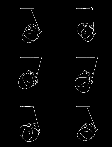
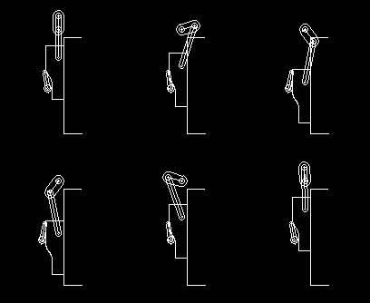
With a cam gear, movements are transmitted non-uniformly. A cam gear consists of a frame, a cam and a follower. The cam contains one or more cam flanks, each sampled by a sampling element on the follower. In almost every case the sampling element is a roller.
The cam is usually the driving part, and the roller follows the cam flank to get the output motion of the follower. Sometimes, however, a cam gear is also operated "backwards" by driving the follower and taking the resulting movement of the cam as output motion.
Cam mechanisms are often combined with linkages which transmit the movement of the cam driven follower to the actual "tool". This tool is the actual output of the cam linkage. By way of distinction, we call the link that directly scans the movement from the cam, "cam follower".
Cams are also commonly used in indexing gears, such as parallel indexing cam gears, cylindrical indexing cam gears and globoidal indexing cam gears.
Take advantage of our many years of experience in the calculation and design of your cams and send us your inquiries!
Skip to ...
- Cam calculation
- Software
- Contact details
- Characteristics
- Alternatives
- Examples
- Cam disks
- Cylindrical cams
- Globoidal cams
- Indexing gears
- Contact types
- Evaluation
- Transmission angle
- Radius of curvature
- Drive torque
- Lifetime
- Pressure
- Material
- Wear
To the homepage of Nolte NC-Kurventechnik GmbH
General information about cam gears
Regularly the desired transfer function is specified for a cam mechanism and, taking account of the kinematics of the transmission, the cam flanks are calculated from this. This process is called "cam synthesis". The cam flanks store the transfer function in coded form, and the kinematics decode the form back into the transfer function.
In "cam analysis", the cam shape is specified and used to determine which transfer function results for a given kinematics. This is interesting if you want to determine the actual transfer function of an existing cam gear from NC or CAD data in order to check or modify it.
If a cam mechanism contains several cam flanks, the degree of freedom is computationally smaller than 1, thus over-defining the gear. Theoretically it then may jam or have slack. If you make the cam flanks exactly enough to each other, so that the transfer functions of all flanks fit exactly enough to each other, the cam gear works in practice still very well. Constructively, steady a slight clamping is often provided to push the slack out of the transmission. Slack is very detrimental to fast-moving mechanisms because the small bumps can cause noise and wear as you run through the slack.
If a cam gear includes only one cam flank, you will need a force-generating element to hold the roller on the cam, eg a return spring, a pneumatic cylinder or - in vertical movements and small number of cycles - simply the weight of the output.
Cam gears are very powerful machine elements for motion control.
Cam gears achieve the highest speed and the most precise processing, in total the best performance, when you have a complicated interaction of movements, as is typical for packaging machines, assembly systems, bending machines, etc.
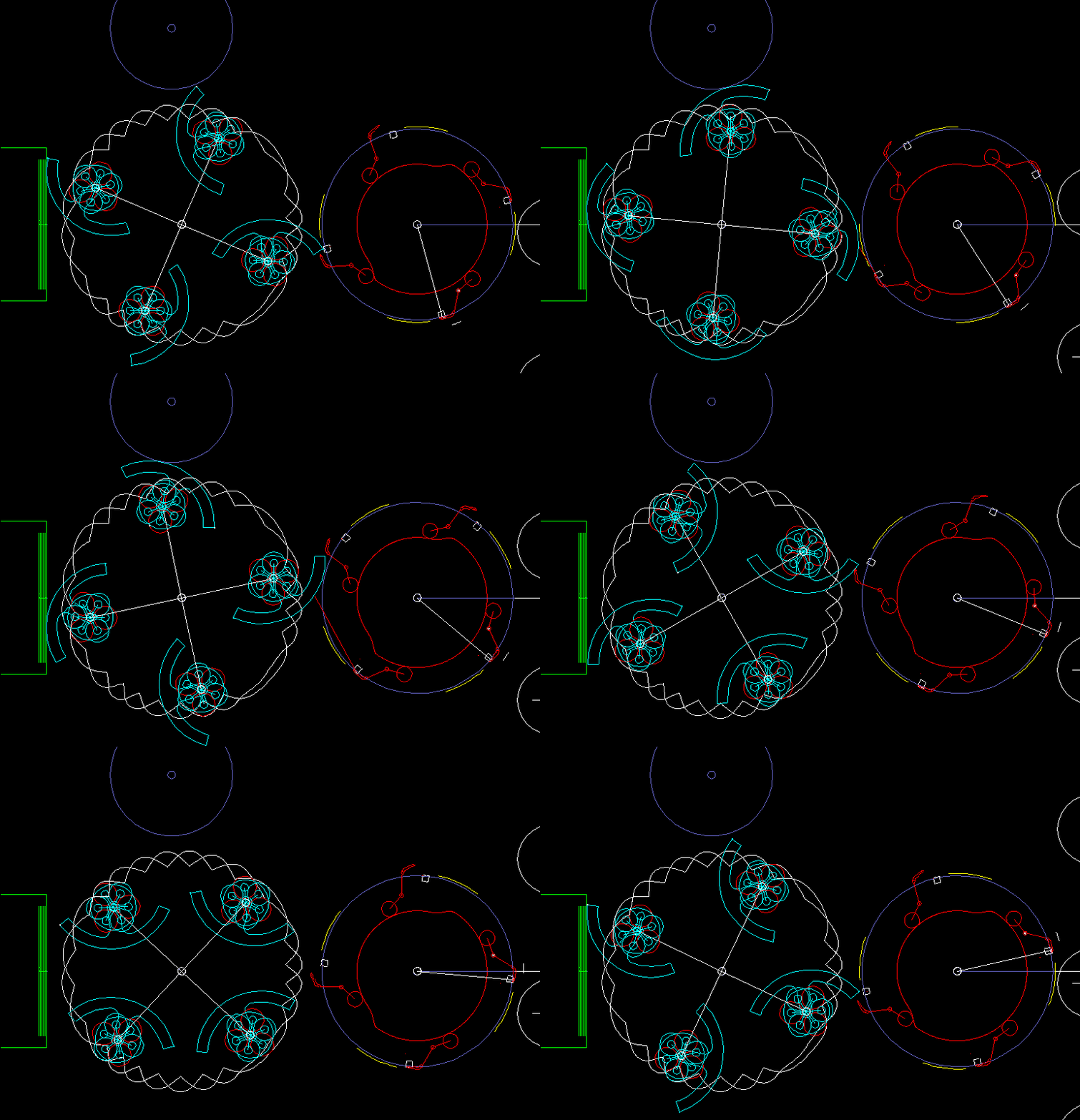
Cams are very well suited for continuous production (as opposed to step-wise production) because the same - mostly stationary - cam can be scanned by several similar follower mechanisms. This is typical when filling, closing and labeling bottles, but also in many other areas.
Example:
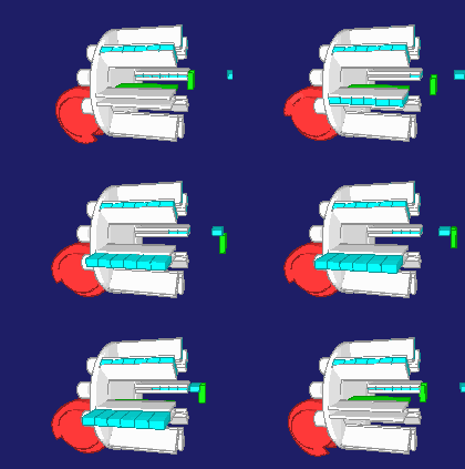
Cam mechanism for labeling bottles (see also the German Wikipedia entry for “Kaltleimetikettierung”).
The simulation shows how labels are glued and applied to bottles. Multiply sampling the same camd paths results in a high performance in continuous operation.
A particular advantage of correctly calculated, manufactured and mounted cam gears is that the movements are automatically executed correctly to each other:
- Referencing is not required
- Nothing can be faulty programmed in the process
- Defects in electronic components are irrelevant
Cam-controlled machines are accordingly easy to commission.
In mechanical cam controls, a worn cam can easily be replaced after 10 or 20 years when you have a DXF or STEP file for the cam flanks. For electronic controls, on the other side, you will probably get no replacements anymore after such a long time.
Alternatives to cam gears:
Linkages
Linkages usually have harmonic, smooth transfer functions, but are difficult to design and usually do not offer enough freedom for the movement design.
Pneumatics
In the case of pneumatics, the transfer function can not be implemented nearly as accurately as with cam gears, so that the individual strokes must be carried out relatively strictly one after the other. For mechanical cams, the correct motion sequence is safe steady if the transitions overlap in time. Compressed air also is expensive.
Servo drives
Servo drives, which we treat with our software and services as well as mechanical cams, have the fundamental disadvantage that the inertia of the motor and gear must always be accelerated when a movement is to be carried out. On the other hand, they are more flexible. If the machine is to be converted to a different format, one servo can simply load another cam profile or another parameter set, while a cam must be replaced mechanically.
It is quite possible and useful to mix mechanical cams and servo drives in one machine. For movements that may remain the same for the entire format spectrum, mechanical cams are provided, while movements that change significantly with the format parameters are more likely to be performed with servo drives. In addition, sometimes very advantageous overall solutions arise by driving a cam gear unsteadily by a servo drive.
Types of cam gears:
You can distinguish ...
... according to the reference surface for the cam flanks:
- a plane in flat cam gears (eg cams or disc cams, rulers, parallel gears)
- a cylinder jacket (eg cylindrical cams or cylindrical cam gears)
- a cone
- a torus (circle around an axis, like a wheelbarrow tire)
- a sphere in spherical cam gears
... after the movement of the cam
- fixed cam with rotating mechanisms
- steadily turning cam
- oscillating turning cam
- non-uniformly continuously rotating cam
- sliding cam (translational, oscillating), eg a cam segment on a press ram
- general planar movement of the cam
- general spatial movement of the cam
... after the movement of the follower
- oscillating
- continuous
- continuous with backward movements
... after the follower, on which the scanning element is placed
- slide mounted in the frame (pestle)
- lever mounted in the frame
- general planar movement (eg roller on the coupler of a four-bar mechanism)
- general spatial movement
... after the scanning element
- circular: roller (cylindrical, convex, optimized shape) or bolt
- flat piece (flat lever, flat ram, "pestle")
- prism
- cone
- ball
- rotationally symmetrical body
- arbitrarily shaped body (eg a bottle in a transport screw)
... according to the number of engagement elements on the cam driven follower
- one: open cam or groove cam
- two: ridge cam or double cam
- more: indexing cam gear
... according to the number of cam flanks per scanning element (roller)
- one: open cam
- two: groove cam
... after the contact type
- Contact by force: one scanning element on one cam flank (open cam)
- Positive locking: the arrangement of the cam flanks itself fixes the position of the scanning elements (rollers)
The general case is that both the cam and the cam-driven parts (followers) are freely movable in space, and that all the scanning elements ("rollers") can be arranged on the followers arbitrarily.
This general case can also be calculated with our software OPTIMUS MOTUS.
Examples of common cam gear types:
- Steadily rotating planar cam with swing lever output
- Steadily rotating cam disc with ram output
- Steadily rotating cylindrical cam with lever output
- Steadily rotating cylindrical cam with slider output
- Fixed cylindrical cam with revolving vertical slide
- Fixed cam with rotating lever drives
- Linear / Ruler cam
- Cylindrical cam ruler
- Cam segment on a slider-crank
- Globoidal cams
- Cycloidal cams
- Indexing cam gears
Example: ruler cam on a press slider:
Examples of special solutions:
- General 3D cam calculation for article insertion in a continuous run
- Cone cam with rollers inside (cable jacket spinning machine)
- Globoidal cam with cranked rollers
- Cylindric cam with diagonal slider motion
- Batter for paper bags
Contact types
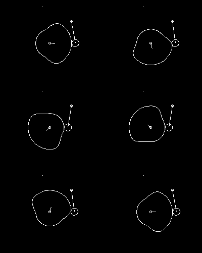
Open: (open cams = external or internal cams)
"Open" means that a force-generating element is needed to ensure contact between cam and roller.
Outside cams: The cam roller is outside the cam profile
Inside cams: The cam roller is inside the cam profile
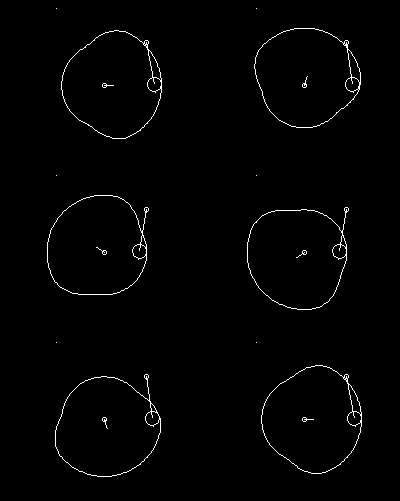
For inside cams, of course, not the entire interior of the cam must be milled free.
Advantages of the open contact:
- Low production costs, since only one cam flank is needed
- Low space requirement
- No backlash between cam and roller, no loss of contact
- No accuracy requirements on the kinematic dimensions of the cam gear to ensure the operability of the cam gear
- Return springs can be used as a safety coupling
- Followers can be disengaged
Disadvantages of the open contact:
- Additional design effort for applying the retention force
- Restoring force also works when it is not needed
- Sum of utilized force and restoring force is relatively large
- Risk of breakage and resonance risk with return springs
For open cam gears, the following aids are used to hold the cam roller on the cam flank:
- Springs with linear characteristic (compression springs or tension springs, compression springs are to be preferred due to lower risk of fatigue failure)
- Pneumatic or hydraulic cylinders
- Weight force
Form-fitting:
Form-fitting means that it is ensured by the shape of several participating cam flanks that the follower position relative to the cam body is well-defined in each gear position. In this case, at least two cam flanks are needed, the shapes must fit exactly to each other, so that the cam gear runs with little backlash and without jamming. Both cam flanks must be calculated correctly to each other, and a corresponding manufacturing accuracy is needed to install the cam flanks on the cam accurately. Form-fitting cams are theoretically over-defined, ie the cam mechanism can only rotate if the shapes of the involved cam flanks match to one another.
Advantages of form-fitting:
- No restoring force required
- Cams only burdened by inertial forces, process forces and friction
Disadvantages of form-fitting:
- High production costs, since several cam flanks are needed
- Cam flanks must be produced geometrically exactly to each other
- Larger space requirements
- Residual slack or additional forces due to tension
- High accuracy requirements on the kinematic dimensions of the cam gear to ensure the running ability of the cam gear
- Safety couplings must be provided additionally
Single groove cams
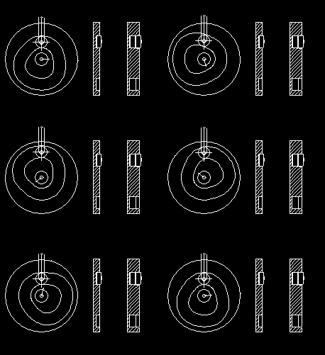
Advantages of single-groove cams:
- Small installation space
- Short roller pin
- Manufactured in one clamping
Disadvantages of single-groove cams:
- Clearance in the groove required (eg fit F7 / h7)
- Wear due to roller rotation change during load changes
- Roller bolt mounted on one side
- Only suitable for low loads and speeds
Double groove cams with overlapping rollers
(see Animation for single groove cams)
Advantages of double-groove cams with two rollers on one axis:
- Rollers braced against each other, low backlash
- Manufactured in one clamping
Disadvantages of double-groove cams with two rollers on one axis:
- Long roller pin, greater deflection / twist under load
- Roller bolt mounted on one side
- Larger space requirements
- Increased production costs due to relief milling with T-slot milling cutters
Double groove cams with adjacent rollers

Advantages of double groove cams with adjacent rollers:
- Rollers braced against each other, low backlash
- Short roller bolts
- Manufactured in one clamping
Disadvantages of double groove cams with adjacent rollers:
- Very large space requirements
- Roller bolt mounted on one side
- Bad transmission angle at swing lever output
Ridge cams
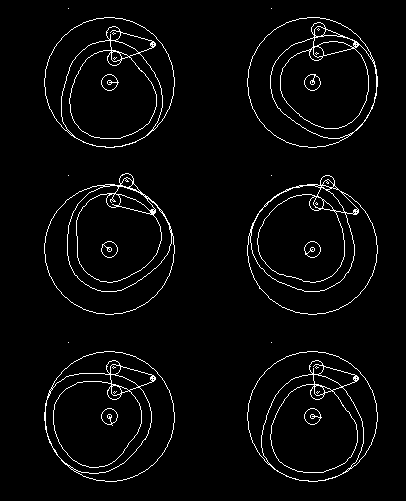
Advantages of ridge cams:
- Short roller bolts
- Rollers braced against each other, low backlash
- Manufactured in one clamping
Disadvantages of ridge cams:
- Ridge thickness is not constant, thin spots possible
- Roller bolt mounted on one side
Double cams (conjugate cams, complementary cams, main and reverse cams, working and return cams):
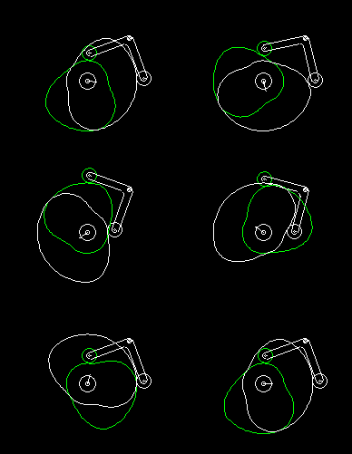
Advantages of double cams:
- Roller pins can be hold on both sides (minimal tilt of the roller)
- Highest loads possible
- Rollers braced against each other
- Suitable for high speeds
Disadvantages of double cams:
- Cams have to be made in two clampings normally
- High production accuracy required
- Big need of space
- Expensive
Reference holes or mounting devices are used to get the cam flanks positioned correctly relative to each other. Highest production accuracy is required if the main and counter cams are each manufactured as individual disks and then mounted on a common hub.
Under certain circumstances, the main and opposite cams are exactly mirror images of each other.
Cams of the same diameter
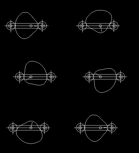
Cams of the same diameter are a special case of the double cams. The special feature is that both individual cam profiles are exactly congruent.
For cams of the same diameter, only one half of the movement diagram can be freely specified (180 degree cam rotation angle). The other half results from the condition that the distance between the two roller centers is fixed, and that both rollers must rest on the same cam.
Evaluation of cam gears
Transmission angle
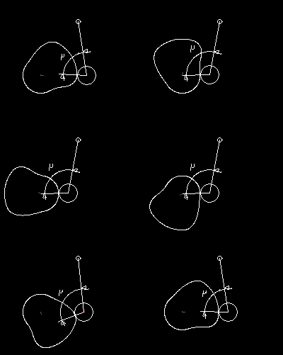
The transmission angle my is a simple kinematic quantity for evaluating the quality of motion transmission in a joint. It is related to the deflection angle epsilon, also called pitch angle or pressure angle.
The deflection angle epsilon in a joint is the angle between the direction in which the movement or the driving force is introduced into the joint, and the actual direction of movement of the joint.
The following applies:
my + epsilon = 90 degrees
my and (180 degrees - my) are equivalent.
The worst value my_min of the transmission angle within the motion cycle is used for the evaluation, regularly the value furthest from 90 degrees. Of the two values my_min and (180 degrees - my_min), the one that is not greater than 90 degrees is used for the evaluation.
For cams with rotating follower, the transmission angle my in the cam joint (contact point between cam and roller) is the angle between the rocker arm (connecting line fulcrum - roller center) and the perpendicular to the camd path.
For cams with sliding follower, the transmission angle my is the angle between the orthogonal to the cam flank in the roller center and the perpendicular to the slider line.
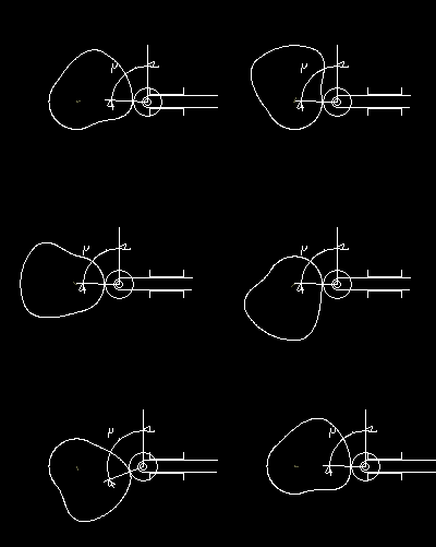
The loads in the output train of the cam gear require a lever position dependent torque respectively force from the follower. The torque on the oscillating lever can be converted with the oscillating lever length into a force that must be applied perpendicular to the lever, ie in the direction of movement of the roller.
If the transmission angle is my = 90 degrees or the deflection angle epsilon = 0 degrees, the contact force between the roller and the cam are just as great. The further the transmission angle deviates from 90 degrees, the greater the contact force between roller and cam, because only the component of the contact force in the direction of movement of the roller is passed on to the output. The transverse component is works directly on the frame via the fulcrum or slider guide.
Larger forces also mean more deformation under load so that the transmission appears more elastic.
The worse the transmission angle, the greater the effective slack in groove cams. The farther the transmission angle is from 90 degrees, the farther is the way of the roller through the slack in a groove cam.
Bad transmission angles make the cam mechanism more susceptible to natural vibrations and collisions.
The course of the transmission angle my should be uniformly distributed around the 90-degree line, ie in both directions of deflection the two extreme values of my should be equidistant from 90 degrees.
The following values can serve as a rough guideline for the cam evaluation:
Fast running cam gear
(eta > 0.07, typical cycle rate: n > 150 rpm):
my_min > 60 degrees
Slow-running cam gear
(eta < 0.07, typical cycle rate: n = 60..150 rpm):
my_min > 45 degrees
Very slow-running cam gear
(typical cycle rate: n < 60 rpm):
my_min > 30 degrees
"Fast" and "slow" are measured rather by the ratio of the cycle rate to the first natural frequency of the power train, by the "tuning" ratio eta = cycle frequency / 1st natural frequency, than by the absolute value of the cycle frequency.
The given specific cycle rates refer to a large part of the practical applications, but not to all.
If the transmission angle is very poor, there is a danger of self-locking on slide guides and on pushed cam levers! The limit depends on the friction conditions in the joints and can vary within wide limits.
Therefore, the transmission angle is a "soft", little meaningful criterion for a concrete cam evaluation.
A cam gear with the worst transmission angle my_min = 40 degrees can work very well in one case and very poorly in another.
It is better to calculate and evaluate the forces and stresses in the joints and to test the excitation of natural oscillations for dynamic considerations, eg by determining the lowest natural frequency in the critical gear position.
Radius of curvature
The radius of curvature gives a clue whether a given movement can be implemented geometrically with a cam of predetermined size.
The radius of curvature rho is the radius of the osculation circle at a point of a camd path.
The osculation circle can be approximated by placing a circle through three close points on the camd path. The radius of this circle is the radius of curvature. In the mathematical sense, the radius of curvature is positive when describing a left turn while traversing the trajectory. For us as cam technicians, the radius of curvature is positive if the cam profile is convex. It is negative if the cam profile is concave. At concave points of the camd path, the cam follower nestles better against the camd path than at the convex points of the cam.
The radius of curvature rho refers to the roller center path.
The radius of curvature rho_p of the cam profile is:
rho_p = rho - roller_radius
The amount of the radius of curvature at the cam profile is smaller in the convex cam areas and larger in the concave cam areas than the amount of the radius of curvature at the roller center path. The difference is equal to the roller radius. With purely kinematic consideration, ie without forces and pressures, one can follow the recommendation that applies in all cam areas:
| rho | > 1.4 roller_radius
It is better, however, to calculate and evaluate the Hertzian pressure in the contact between cam and roller. It turns out that the kinematic criterion is far too strict in many cases, making optimization difficult.
Undercut occurs when the profile curvature radius rho_p theoretically becomes smaller than 0:
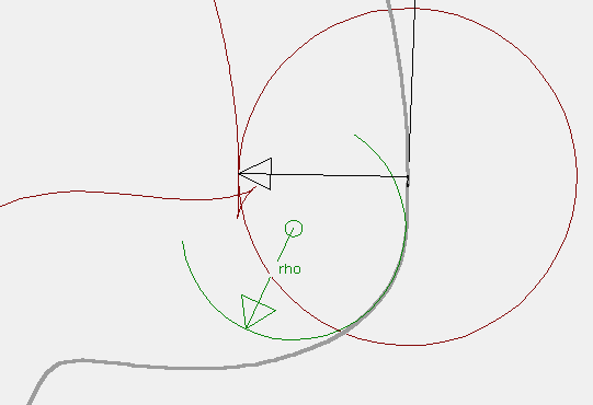
This is the case when the lateral acceleration of the roller center with respect to the cam coordinate system is too large in relation to the path speed.
When cams with steady drive have undercut, probably the output acceleration is too large, but this is only roughly true.
Undercut should be avoided in any case:
- A cam with an undercut can not implement the given transfer function because the theoretical cam profile cuts itself off.
- There are two jerks as the reel moves up and down to the top.
- A groove, ridge or double cam has slack, resulting in shocks.
- For cams with return spring very high surface pressures occur when the cam profile tip is loaded.
- Undercut camd profiles also cause technical difficulties when you try to extrude the cam in a CAD system and - in the case of cam disks - when manufacturing on CNC machines.
Drive torque
The maximum amount of cam drive torque must be less than the maximum permissible torque of the drive (motor, gearbox).
The permissible peak torque is usually dependent on the drive speed.
To avoid thermal overload, the effective value of the cam torque (root mean square) must be smaller than the rated torque of the motor.
Air or water cooling significantly increases the permissible permanent torque (rated torque) of the motor.
If several cams are driven by one motor, then the torque sum (superimposition of all individual torque cams) should be considered and optimized!
The overall cam torque should have low extreme values and be smooth in order to avoid vibration excitation due to the dynamic alternation of the drivetrain.
Chains should not be used as a drive element for high-speed mechanisms due to the low rigidity and because of the polygon effect!
Roller lifetime
With the dynamic load rating of the selected cam follower, the nominal service life for the cam follower can be determined with the courses of the contact force between roller and cam and the roller speed. The catalogs from the bearing manufacturers provide more information on coefficients that take operating conditions into account.
Our software OPTIMUS MOTUS contains a database of common roller types and calculates the nominal life for all listed rollers with the desired nominal diameter.
Hertzian pressure
Hertzian pressure is the most important factor for evaluating the material load in rolling contact between cam and follower.
If the pressure exceeds the permissible value, pittings are formed over time and the surface (usually the cam) is destroyed.
Besides the Hertzian pressure we also know the Stribeck pressure, but this is much less common. The Stribeck pressure limits for a material are completely different than for the Hertzian pressure!
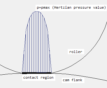
In the middle of the contact, the material is compressed significantly more than at the edges, so that the material in the middle suffers the highest stress. The pressure curve in the picture is simplified. Tilting and lubricant change the shape of the pressure curve over the contact zone.
Sliding parts additionally stress the material!
The following bearing types are used to scan the cam:
- Cylindrical rollers: line contact between cam and roller (rectangular contact surface)
- Crowned rollers with constant crowning radius: point contact between cam and roller (elliptical contact surface). The pressure values are independent of the cam width, as long as the cam is wider than the pressure ellipse is long.
- Crowned rollers with optimized profile (non-constant crowning radius)
The Hertzian pressure helps to estimate the lifetime of the cam flank with respect to pittings. Pittings are the most common cause of load-related cam failure.
Our OPTIMUS MOTUS software estimates the expected service life based on the occurring Hertzian pressure and the surface hardness of the cam flank.
Materials
We find that the following materials are often used for cams:
Steel:
42 Cr Mo 4
34 Cr Ni Mo 6
34 Cr Al Mo 7
31 Cr Mo V 9
16 Mn Cr 5
20 Mn Cr 5
17 Cr Ni Mo 6
C 45
90 Mn Cr V 8
100 Cr 6
Molding:
GGG-60
GG 25
Plastic:
PA 12 G
PET-GL
PET
PA 12.6
The steel materials are often heat treated by the following methods, in particular to increase their wear resistance in terms of pitting and sliding:
Tempering
Heating to temperatures below 723 degrees Celsius to reduce internal stress, usually after hardening
Carburizing
For low alloy steels as a preparation for hardening
Carbonitriding
Enrich surface layer <0.5 mm with nitrogen and carbon, followed by quenching, to increase the hardness of low alloyed and tempered steels
Case hardening
(Carburizing, hardening and tempering) at carbon content <0.25%. Hardening depth between 0.5 and 2 mm, with special methods up to 6 mm. Hardness distortion usually requires grinding. Very hard surface layer, soft core.
Surface hardening
(Flame or induction heating and quenching). From about 0.3% carbon content. Gentle hardness slope (surface hardness, transition zone, soft core). Edge layer thickness Rht up to approx. 1.2 mm. Distortion from hardening usually requires grinding.
Hardening
Heating above 723 degrees Celsius (austenite phase) and rapid cooling to obtain martensitic structure. Subsequently, temper (relax).
Quenching and tempering
Hardening with tempering at very high temperature (up to 700 degrees). Goal: high strength and high toughness.
Nitriding
(Gas, plasma, bath nitriding) Enrich the surface layer with nitrogen. Hardness, wear resistance, fatigue strength and corrosion resistance increase. Nitriding hardness depths between 0.1 and 0.8 mm. With special processes up to 1.2 mm. Low distortion, but layer thickness increases.
Almost all steels and cast iron can be nitrided with any pretreatment. Nitriding time: 40 to 90 hours.
Recommendation: Compensate workpieces before nitriding and anneal stress-relieved.
Base material should have high strength, so that the camd track surface does not flake off under continuous load, because the nitriding layer is brittle.
Vacuum hardening
For precision components.
Annealing
(Soft annealing, normalizing, stress relieving, intermediate annealing) High dimensional accuracy parts should be stress relieved prior to machining so that they do not deform during turning and milling.
Wear
For cams, the following wear mechanisms are particularly common:
Wear from rolling (fatigue wear):
Some symptoms:
- Plastic deformation
- Surface flaking
- Crumbling of the edges of the cam flank
- Pittings
Possible causes:
- Fatigue due to load changes and load
- Too high pressure
- Too low surface hardness
- Too low hardening depth
- Insufficient core strength of the material
Operational chatter marks:
(in contrast to production-related chatter marks with lower pitch)
Some symptoms:
- Regularly occurring undulating bumps (0.01 to 0.02 mm deep)
- During operation over days or weeks vibrations build up, operation becomes noisy, resulting in malfunctions
Possible causes:
- Vibration excitation by the cam gear itself
- Backlash in the cam mechanism
- Gaps on the cam surface
- Roller and cam axis not parallel or orthogonal (results in edge pressure)
- Jerky or bumpy movement
- External vibration excitation, eg due to the drive train (polygonal effect of one chain drive, retroactive vibrations of another cam gear)
Sliding wear:
Some symptoms:
- Grooves in sliding direction
- Roughened surface by micro-welding
- Surface abrasion
Possible causes:
- Solid and mixed friction due to insufficient lubrication
- Surface too rough
- Slippage between cam and roller (eg system change in groove cams)
If a cam fails prematurely due to wear, the cause can sometimes be hard to find. With our many years of experience, we will help you!
To the homepage of Nolte NC-Kurventechnik GmbH
Start Kinematics Mechanisms Indexing Servo+PLC MotionDesign Training Service CamCalculation Software Imprint PrivacyPolicy
Features Alternatives Examples CamDisks BarrelCams GloboidalCams IndexingCams AlignmentTypes Evaluation TransmissionAngle Curvature Torque Durability Pressure Material Wear
29/10/18
• Software OPTIMUS MOTUS ®
• All types of Cam Calculations
• Performance Optimizations
• Energy Efficiency in Machines
• Trainings and consulting
• App and Software Development
• SPS Motion Software
Cams, Mechanisms, Motion Design. Faster Machines. Since 1965.
